Do you have a question about the Inter-m A-120 and is the answer not in the manual?
Alerts user to uninsulated dangerous voltage and advises against removing covers or servicing.
Warns against exposing the unit to rain or moisture to prevent fire or shock hazards.
Specifies suitable environments, avoiding heat, dust, moisture, and vibration for optimal performance.
Provides a list of 14 crucial safety instructions for installation and operation.
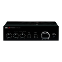
Knobs for continuous control of high and low frequency response, up to 12dB cut or boost.
LED indicating active protection circuitry due to overheating or power limiting.
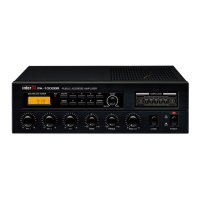
Six-segment LED meter showing amplifier's output level in RMS.
Knobs for continuous volume control of Mic Inputs 1-3.
Knobs for continuous volume control of Aux Inputs 1 and 2.
Knob for continuous control of the overall output volume.
Button to turn the unit on/off, indicated by a Power LED.
Connection point for the AC power cord to the outlet.
Inputs for connecting line-level sources like CD players or tuners.
Terminals for connecting speakers, supporting 4 conventional or 70V/100V high-impedance.
1/4" phone jacks for standard mic-level input with 600 impedance.
Control to adjust attenuation level for other inputs when Mic Input 1 is active.
Parallel connection for low-impedance speakers to the 4 terminal and COM terminal.
Connection with matching transformer to 70V or 100V terminals for distributed systems.
Details rated output/impedance, frequency response, T.H.D., S/N, and input sensitivity.
Covers power source, consumption, weight, and dimensions.
Guidance on troubleshooting operator error and contacting warranty providers for issues.
Information on how to obtain a schematic diagram and parts list for the unit.
Notes products' compatibility with local AC power requirements from legitimate sources.
States that no optional items are available for this specific product.
| Power Output | 120W |
|---|---|
| Frequency Response | 20Hz - 20kHz |
| THD | < 0.5% |
| S/N Ratio | 80dB |
| Power Source | AC 220-240V, 50/60Hz |
| Power Output per channel | 120W (Mono) |
| Signal-to-Noise Ratio | Better than 80dB |
| Input Impedance | 10kΩ |
| Cooling | Convection |