EasyManuals Logo

Inter-m P-2000 Operating Manua

Inter-m P-2000
10 pages
To Next Page IconTo Next Page
To Previous Page IconTo Previous Page
Page #6 background imageLoading...
Page #6 background image
55
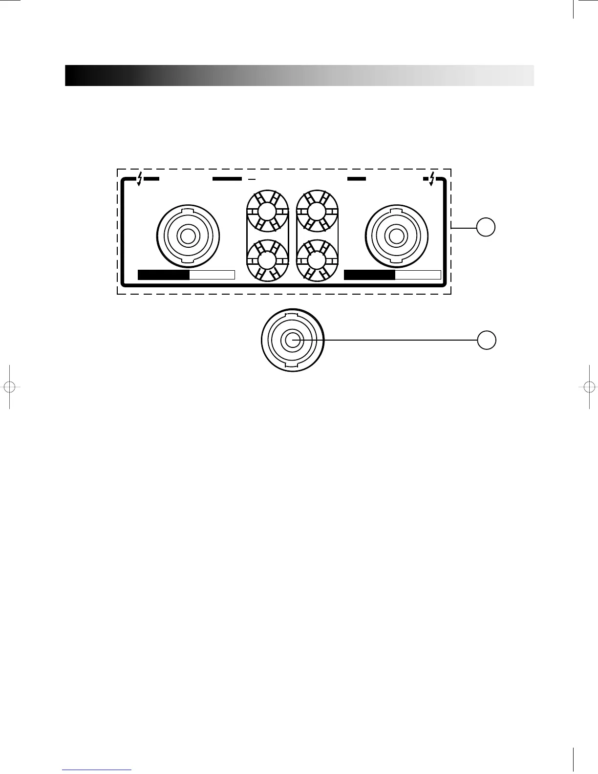
4. OUTPUT CONNECTORS
Output terminals are dual five-way binding posts and speaker connectors.
* When speakers are connected amplifier, please make sure correct connection of each pin, and refer
speaker pin number.
1) Binding Post
• ST MODE
{
RED: HOT
BLACK: GROUND
• BRIDGED MONO MODE
{
RED(CH1): HOT
RED(CH2): COLD
2) SPEAKON
(A) PIN 1+ : HOT
PIN 1–: GROUND
PIN 2+, 2 : NOT CONNECTED
(B) STEREO MODE BRIDGED MONO
PIN 1+ : CH1 HOT PIN 1+ : HOT (POSITIVE)
PIN 1– : CH1 GROUND PIN 2+ : COLD (NEGATIVE)
PIN 2+ : CH2 HOT
PIN 2: CH2 GROUND
CONNECTOR
PIN 1+ POS
PIN 2+NEG
SEE MANUAL, BR. SW.
BRIDGED
4 MIN.
STEREO
2 MIN. / CH.
CONNECT
(CH 1) PIN 1+, PIN 1-
(CH 2) PIN 2+, PIN 2-
DUAL CHANNEL OUTPUT CONNECTOR
BRIDGED MONO
( + )
CHANNEL 1
CHANNEL 2
( )
PIN 1-GND
PIN 1+ POS
PIN 1-GND
PIN 1+ POS
B
A

Other manuals for Inter-m P-2000

Questions and Answers:

Question and Answer IconNeed help?

Do you have a question about the Inter-m P-2000 and is the answer not in the manual?

Inter-m P-2000 Specifications

General IconGeneral
BrandInter-m
ModelP-2000
CategoryAmplifier
LanguageEnglish

Related product manuals