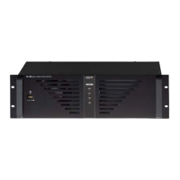
66
STEREO MODE AND BRIDGE MODE
• STEREO MODE
In this mode, channels A and B operate independently (typical stereo amplifier). Channel A input signal feeds
channel A power amp, and channel B input signal feeds channel B power amp. In this mode, the minimum
speaker impedance per channel is 4Ω.
• BRIDGE MODE
In this mode, channels A and B are bridged together and work as one mono amplifier. In this mode, the
minimum speaker impedance is 8Ω.
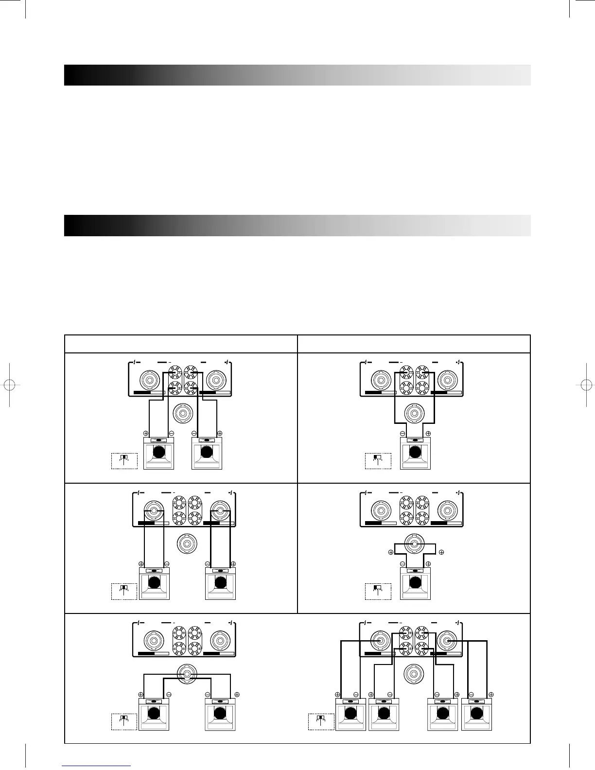
SPEAKER IMPEDANCE AND CONNECTION
P series amplifier has three operating modes: Stereo, parallel and Bridged mono, and allows you to connect
multiple speaker systems in parallel. Therefore, the minimum speaker impedance various depending on the
combination of these speakers. Be sure that the speaker impedance falls below the specified impedance.
The figures below show the examples of connection in Stereo mode and Bridge mode, and speaker systems
connected in parallel in Stereo mode, and the respective minimum impedance.
STEREO MODE BRIDGE MONO MODE
CONNECTOR
PIN 1+ POS
PIN 2+NEG
SEE MANUAL, BR. SW.
CONNECT
(CH 1) PIN 1+, PIN 1-
(CH 2) PIN 2+, PIN 2-
DUAL CHANNEL OUTPUT CONNECTOR
CONNECTOR
PIN 1+ POS
PIN 2+NEG
SEE MANUAL, BR. SW.
CONNECT
(CH 1) PIN 1+, PIN 1-
(CH 2) PIN 2+, PIN 2-
DUAL CHANNEL OUTPUT CONNECTOR
CONNECTOR
PIN 1+ POS
PIN 2+NEG
SEE MANUAL, BR. SW.
CONNECT
(CH 1) PIN 1+, PIN 1-
(CH 2) PIN 2+, PIN 2-
DUAL CHANNEL OUTPUT CONNECTOR
CONNECTOR
PIN 1+ POS
PIN 2+NEG
SEE MANUAL, BR. SW.
CONNECT
(CH 1) PIN 1+, PIN 1-
(CH 2) PIN 2+, PIN 2-
DUAL CHANNEL OUTPUT CONNECTOR
CONNECTOR
PIN 1+ POS
PIN 2+NEG
SEE MANUAL, BR. SW.
CONNECT
(CH 1) PIN 1+, PIN 1-
(CH 2) PIN 2+, PIN 2-
DUAL CHANNEL OUTPUT CONNECTOR
CONNECTOR
PIN 1+ POS
PIN 2+NEG
SEE MANUAL, BR. SW.
CONNECT
(CH 1) PIN 1+, PIN 1-
(CH 2) PIN 2+, PIN 2-
DUAL CHANNEL OUTPUT CONNECTOR
(STEREO MODE)