PUBLIC ADDRESS AMPLIFIER
6
PA-935N
16. MIC2 / AUX SELECTOR SWITCH
T
his switch is used to select between MIC2 and AUX. MIC2 input becomes effective on this switch being
set right side,. The other hand, AUX input become effective on this switch being set left side.
17. MIC3 INPUT (EURO CONNECTOR, -50dB, BALANCE)
Connect the microphone.
18. CD / SATELLITE INPUT (RCA PIN JACK, -3dB, UNBALANCE, MIXED L/R)
Connect the line level apparatus. This connector effect the 16 SELECT switch is set left side.
19. MIC3 / CD / SATELLITE SELECTOR SWITCH
This switch is used to select between MIC3 and CD/SATELLITE. MIC3 input becomes effective on this
switch being set right side,. The other hand, CD/SATELLITE input become effective on this switch being
set left side.
20. TELEPHONE INPUT
This input is used to connect to a telephone exchange system for paging purposes.
NOTE : When signal is present on the Telephone Input terminal, all other input signals are ducked.
21. TELEPHONE INPUT LEVEL CONTORL
This VR provides continuous control of the volume of TELEPHONE signal.
Even if it turns to counterclockwise end, slight volume remains.
22. TLELPHONE IN DUCKING DEPTH CONTROL
This VR provides continuous control of the ducking depth of all signals.
Ducking effect will be acquired if it turns counterclockwise.
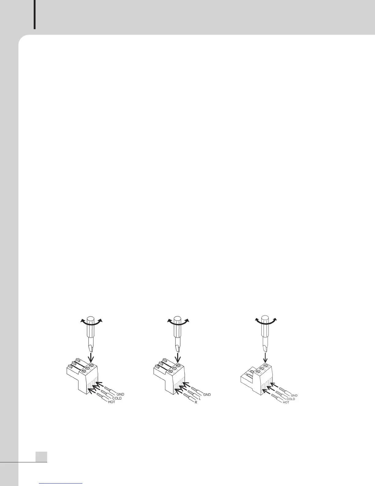
<HOW TO CONNECT>
MIC1,2,3 input AUX input TELEPHONE input