1
REQUIRED TEST EQUIPMENT
1. Oscilloscope
2. 1kHz audio sine wave generator
3. Digital multimeter
4. 8ohm resistive load (rated for at least 750W)
IDLE CURRENT (V-3000/4000)
1. Setting
Set the master volume controls minimum.
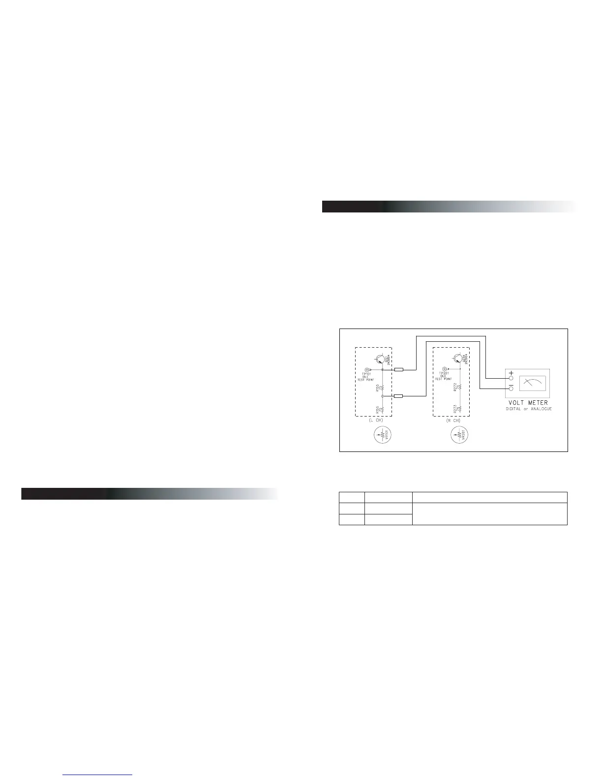
2. Connection
3. Adjustment
a. Measure the DC voltage across the resistor R155 and R272. adjust VR101 and VR201.
b. Adjust VR101 until the DC voltage is within the range as below table.
c. Repeat the adjustment(a,b) for the other channel.
;ΠΕΖΝ ͵ʹΧΠΝΥΒΘΖΣΒΟΘΖ ͲΕΛΦΤΥ
· Ξ·ρΞ·
· Ξ·ρΞ·
ʹΙΒΟΟΖΝ͵ʹΧΠΝΥΒΘΖΒΔΣΠΤΤԽΒΕΛΦΤΥ·
ʹΙΒΟΟΖΝ͵ʹΧΠΝΥΒΘΖΒΔΣΠΤΤԽΒΕΛΦΤΥ·
Electrical Adjustment Procedure
Specifications
Electrical Parts List
Top and Bottom View of P.C.Board
Wiring Diagram
Block Diagram
Schematic Diagram
1
2
3~8
9~14
15
16
17~26
· · · · · · · · · · · · · · · · · · · · · · · ·
· · · · · · · · · · · · · · · · · · · · · · · · · · · · · ·
· · · · · · · · · · · · · · · · · · · · · · · · · · · · · · ·
· · · · · · · · · · · · · · · · · · · · · · · · · · · · · ·
· · · · · · · · · · · · · · · · · · · · · · · · · · · · · · · ·
· · · · · · · · · · · · · · · · · · · · · ·
· · · · · · · · · · · · · · · · · · · · · · · · · · · · · · · ·
CONTENTS