11
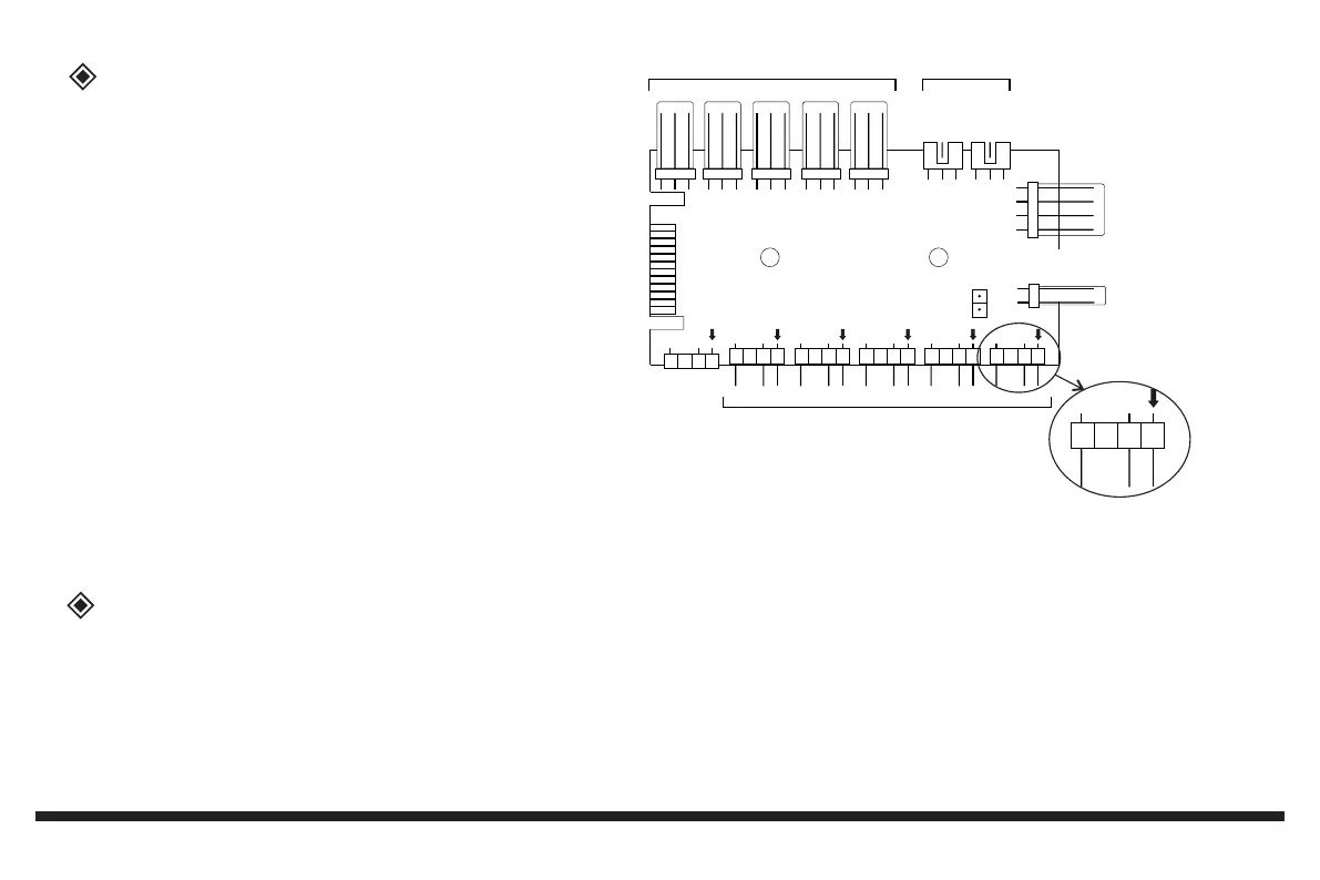
Connection RGB / PWM controller
1. 3pin connectors for fans
2. Imput for PWM singal from motherboard (CPU fan connector)
3. 3pin connectors for RGB, 5V digital
4. SYNC connector to mainboard
5. Connector to the LED switch
6. Power input (S-ATA connector)
7. Test jumper for PWM regulation
8. Connector RGB strip
At the 4pin connections (3) both the illumination of RGB fans as well
as pure RGB strips are connected and then controlled by the LED
switch on the case. With suitable distributors (depending on the
performance of the mainboard) other RGB elements can be connected
to these ports. Please note that the total output power of the board must
not exceed 48W per color channel.
Please note the connection diagram of the built-in board.
Incorrect connection may damage the board.
After turning on the computer for the first time, the light control is in the Off state.
Press the switch briefly to switch on the light control.
The control board stores the last set effect.
Each time you press the button, you can change the light.
To turn off the RGB control, press the LED switch for more than 3 seconds.
The computer always reboots
The light control switch does not work
Neither the fans nor the light work
Fans do not turn
Make sure connector 2 and 4 are plugged correctly and polarity is correct.
Check if the switch is connected to socket 5.
Check if the module is connected to the power supply via plug 6 and gets power
Check if there is a fan connected to port „FAN1“. Some motherboards are sending a faulty PWM- signal and the controller
is not able to process it. In this case you need to disconnect all fans from the controller and connect them to the
PWM-slider on the top of the case. Other solution is to put a jumper on “7”.
Both solution cause the fans to turn at full speed and they can´t be regulated anymore.
When operating the board via port 4 directly on the mainboard, the switch via port 5 is disabled.
Test
Rainbow2Rainbow3
Rainbow4
Rainbow5
MB Rainbow
PWM IN
FAN 1FAN 2FAN 3FAN 4FAN 5
SATA
SW
1
2
3
4
5
6
Rainbow1
7
Strip 1 - 2
8
Error causes
Rainbow1
5V
D
G