AC40 Instructions for Use - US Page 9
3 Getting Started - Setup and Installation
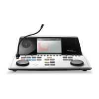
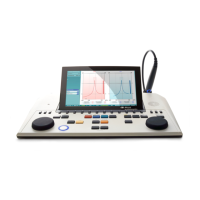
The following shows an overview of the AC40:
The top left part of the AC40 (display holder) contains the two monitor speakers.
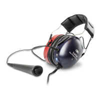
The left side of the instrument contains two mini jack connectors for a microphone and a headphone – or
a headset. This is used for talkback headphone/speaker (TB) and talk forward microphone (TF). Next to
that two USB connectors are located. These can be used for connecting external printers/keybaords and
USB sticks for installing firmware/wave file material.
A swan neck microphone can be plugged into the top part of the instrument by top part of Talk Forward
button. This can be used for talk forward. When not in the swan neck microphone can be placed
underneath the display. Please refer to the section about patient communication for more.
The upper right side of the instrument holds the on/off switch of the instrument.
Make sure that the audiometer is placed so that the patient cannot see/hear the clinician’s use of the
instrument.
Back Panel – connectors – see next page
and
Headphnoe
(Headset)
mini jacks +
2 USB
connectors
on/off
display &
buttons/dials
peaker