Interflex Datensysteme GmbH 4/8
2 Mounting the Terminal
2.1 Installation site
Please observe the following recommendations:
Permitted ambient conditions for the terminal
Minimum distance of 10 cm between the connecting cables and the nearest power lines
Recommended installation height: 1250 mm.
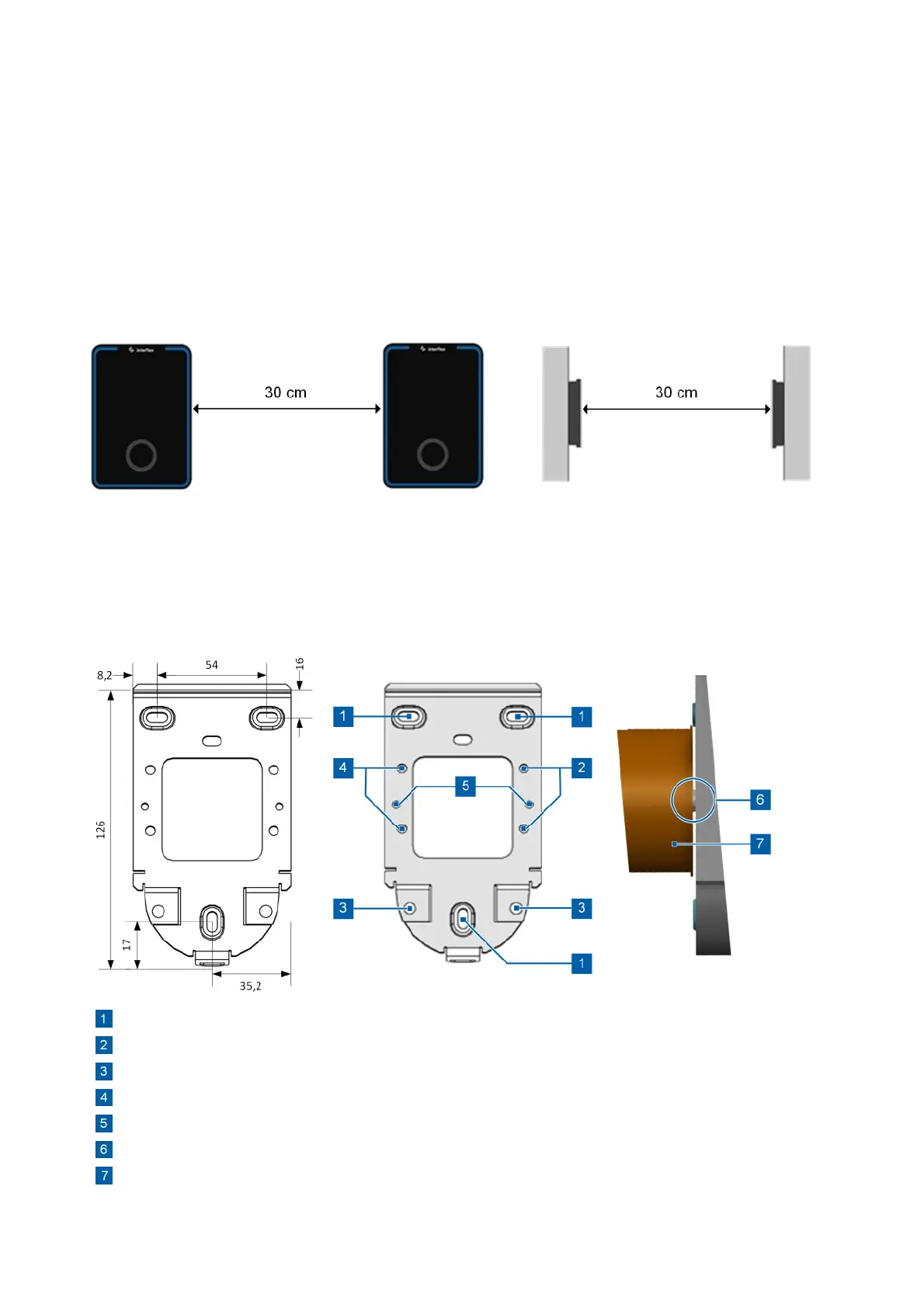
Minimum distances between RFID and BLE devices
If several RFID devices are mounted too close together, mutual interference may occur. Thus, the following
minimum distances must be maintained:
The minimum distance for back-to-back installation depends on the nature of the wall in between.
Please make sure that all BLE devices within range are recognized and that respective doors are opened
(according to the permission) when the "auto-booking" function is enabled.
2.2 Fastening the Back Panel of the Housing
The following figure shows the back panel of the housing and its side view with appliance case and mounted
terminal.
3 bore holes for wall mounting
Threaded bushing for fastening an optional 24 V interface (75-5735-0004)
Threaded bolt for securing the PoE connector
Threaded bushing for fastening an optional I/O controller board (75-700-0141)
Bore holes for mounting via appliance case
Plain washer
Flush box
Recommended installation height: 1250 mm
 Loading...