Interflex Datensysteme GmbH 6/7
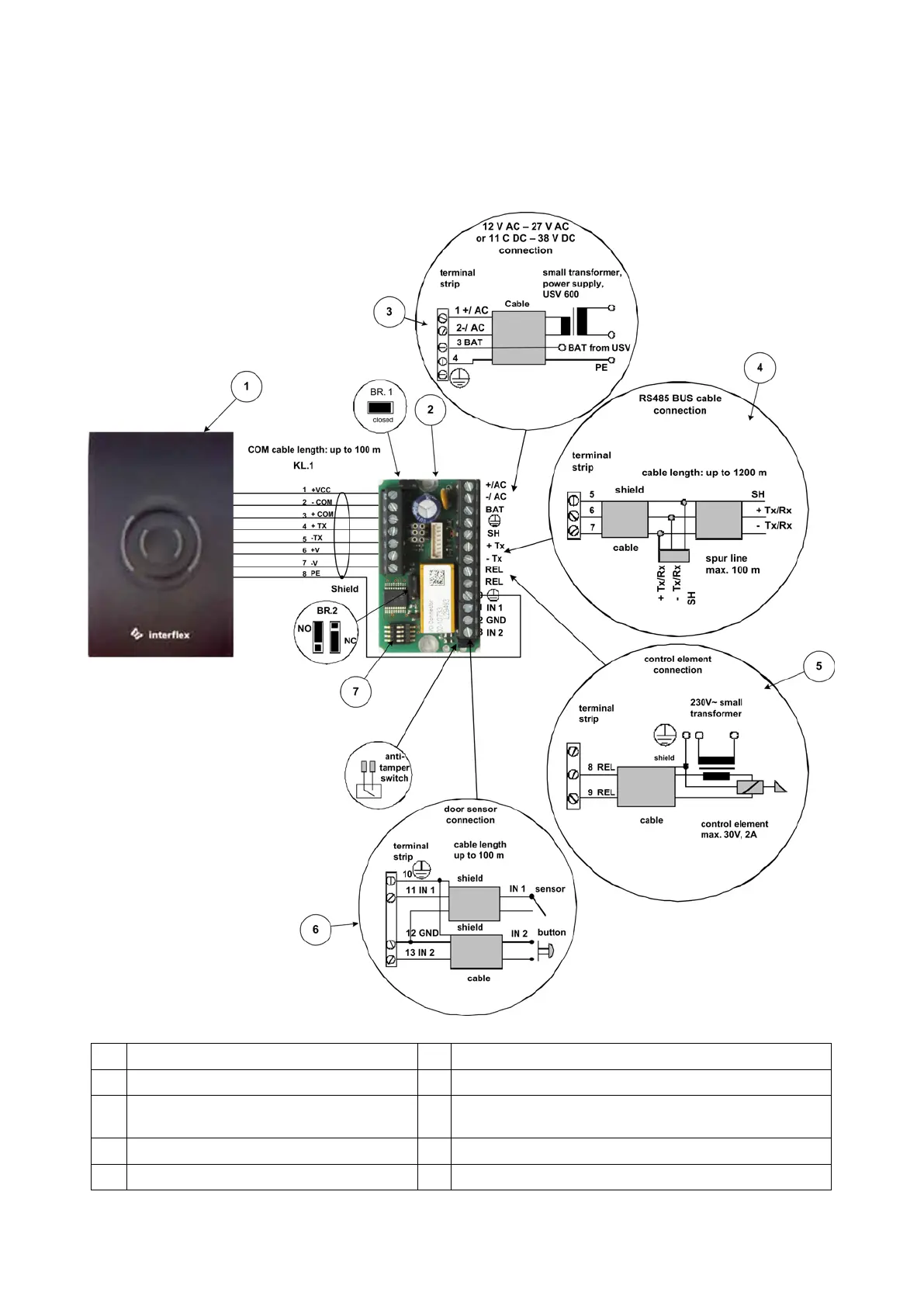
9 Connections on the I/O Controller Board
To maintain the required EMC values, the protective earth conductor and also the cable shields must be
connected as shown in the figure below.
For information on the connection of the RS485 data line to a terminal controller or master terminal, please
refer to the installation and wiring instructions included in the delivery of the respective device.
1 IF-800/W02 6 Example: Door monitoring connection
2 I/O controller board 7 Address switch
3 Power supply example Br1 Bridge is removed if the I/O controller board is to be used
as an expansion
4 Example: Connection of the RS485 data line Br2 Setting the relay output to normally open / normally closed
5 Example: Connection of an actuator Br3 Contact for monitoring the housing