Interflex Datensysteme GmbH 5/8
3.5 Hardware Address Setting
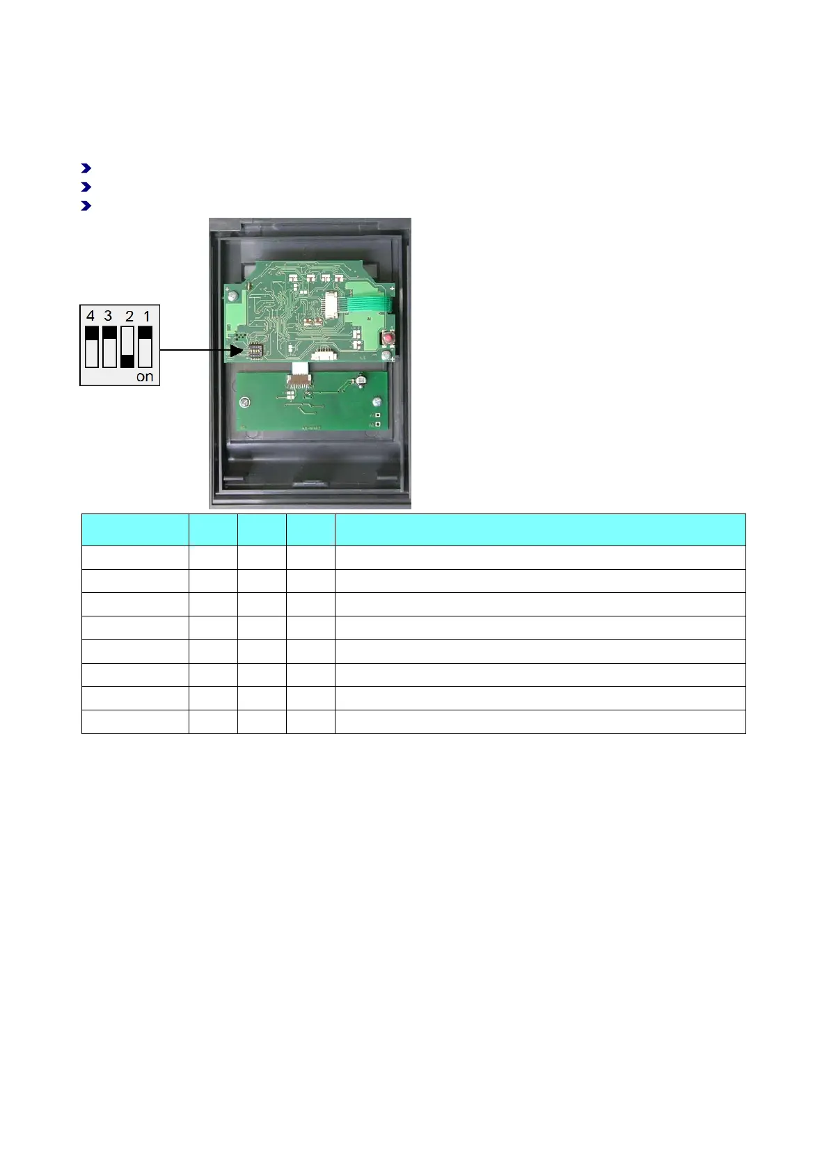
In order to specify the device address, up to 4 address switches must be set to the correct position
on the MPU board.
Before setting the switches, check the bus address range. Addresses may not be assigned twice.
Set address 1 for the first slave terminal, address 2 for the second slave terminal, and so forth.
For the connection to a master terminal, set address 2 for the first slave terminal, and so forth.
Address 1 OFF OFF OFF OFF (not required if connected to a master terminal)
Address 2 OFF OFF OFF ON
Address 3 OFF OFF ON OFF
Address 4 OFF OFF ON ON
Address 5 OFF ON OFF OFF
Address 6 OFF ON OFF ON
Address 7 OFF ON ON OFF
Address 8 OFF ON ON ON
3.6 Wiring
Power supply
Power can be supplied:
via a 12 VAC - 24 VAC power transformer.
via a 12 VAC - 24 VAC low-voltage power supply unit.
via an IF-79 I/O BUS panel (max. 100 m).
Connecting the BUS cable
The IF-810/IF-811 terminal is connected to BUS1, BUS2 or BUS3 of a controller.
Connecting the I/O controller board
The I/O controller board is used for controlling electric actuators. If access control is not required, the I/O
controller board can be omitted. In that case, connection takes place directly on the terminal board using a
cable of up to 100 m length.