Interflex Datensysteme GmbH 2/8
3.1 Cables and Cable Types
No.
Max. Length Cable Cores
1 BUS cable from controller to terminal (slave) installed furthest away 1,200 m 4 x 2 x 0.6 mm²
1a Branch cable from bus to installation site of terminal (slave) 100 m 4 x 2 x 0.6 mm²
2 110/ 230 V mains cable to transformer or DC power supply unit
2a Low voltage cable to terminal board (3) 4 x 2 x 0.6 mm²
We recommend:
installing a separate, fuse-protected circuit.
supplying operating voltage via a separate cable (2a) to avoid interference.
keeping a minimum distance of 30 cm between the slave terminal and other systems with RFID readers.
keeping a distance of 10 cm between connecting cables and power lines.
The following installation procedure has been proven and tested:
1. Install the cables.
2. Install the power supply.
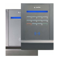
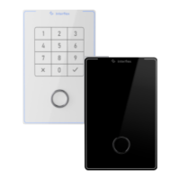
3. Mount the back panel of the IF-810/IF-811. If the terminal is to be used for access control, an I/O
controller board must also be mounted in a secured area.
4. Set the address.
5. Close the housing.
6. Put the IF-810/IF-811 into operation.
3.2 Shielded Cables
To guarantee trouble-free operation, we recommend the use of shielded cables.
Operation, however, is also possible with unshielded cables. Data transfer problems must be examined on a
case-by-case basis. Where necessary, a shielded cable must be used for the corresponding devices.