Interflex Datensysteme GmbH 7/8
The I/O controller board allows for access control. The board can switch electric door
openers up to max. 30 V 2 A via an NO or NC contact. It must be separated from the IF-810/IF-811 terminal
and installed in a secured area, e.g. in a Hensel installation box (no. 78-700-0146) or a DIN appliance case.
In order to prevent malfunction and manipulation, the I/O controller board may not be installed in the housing
of an IF-810 or IF-811 terminal.
3.7.1 Circuit Examples
Power supply (2)
The IF-810/IF-811 terminal can be supplied with 18-24 V AC/DC via the I/O controller board.
Connection of RS485 data cable (3)
The RS485 data cable is connected to terminals 5, 6 and 7. The data cable may have a max. length of 1200
m. If a spur line is connected to the data line, the length of the spur line may not exceed 100 m.
Connection of a control element (4)
An actuator, shown as a door opener in the figure, is connected to terminals 8 and 9. The actuator is
controlled by the relay of the I/O controller board and can switch a maximum of 30 V and 2 A. Via the bridge
(1b), the relay contact can be changed from normally open (NO) to normally closed (NC). If two relay outputs
are required, a further I/O controller board is needed.
Connection of sensors (5)
Two sensors can be connected to the I/O controller board. Usually, one door contact and one door opener
are connected. If more than two sensors are required, a further I/O controller board is needed. The bridge
(BR4) must then be removed on the second I/O controller board.
To avoid interferences, use shielded cables for the connection between the I/O
controller boards and the terminal.
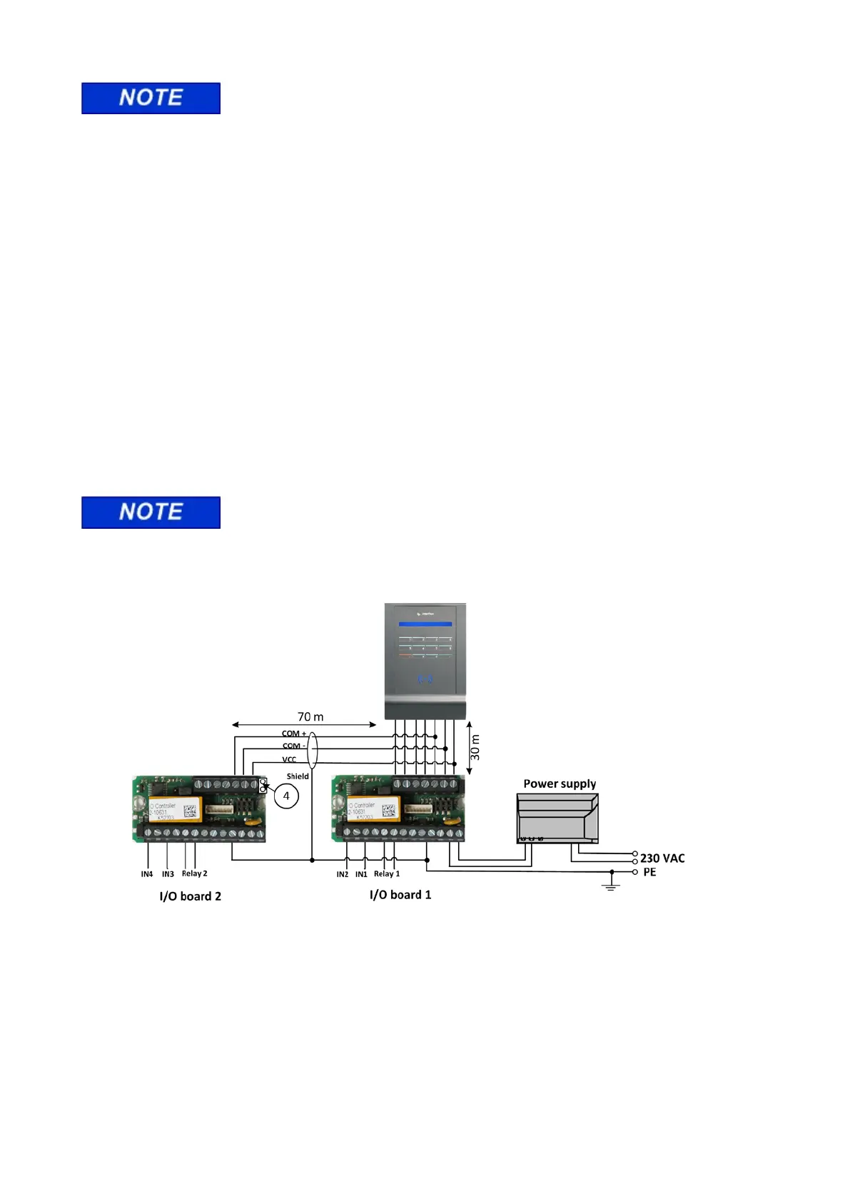
3.8 Connecting two I/O controller boards
3.9
For technical reasons, the total length of the COM cable is limited to 100 m. The length of the COM cable is
to be reduced as in the example to ensure that a total length of 100 m is not exceeded. The bridge (4) on I/O
controller board 2 must be removed.