Piping direction
C. Piping Direction
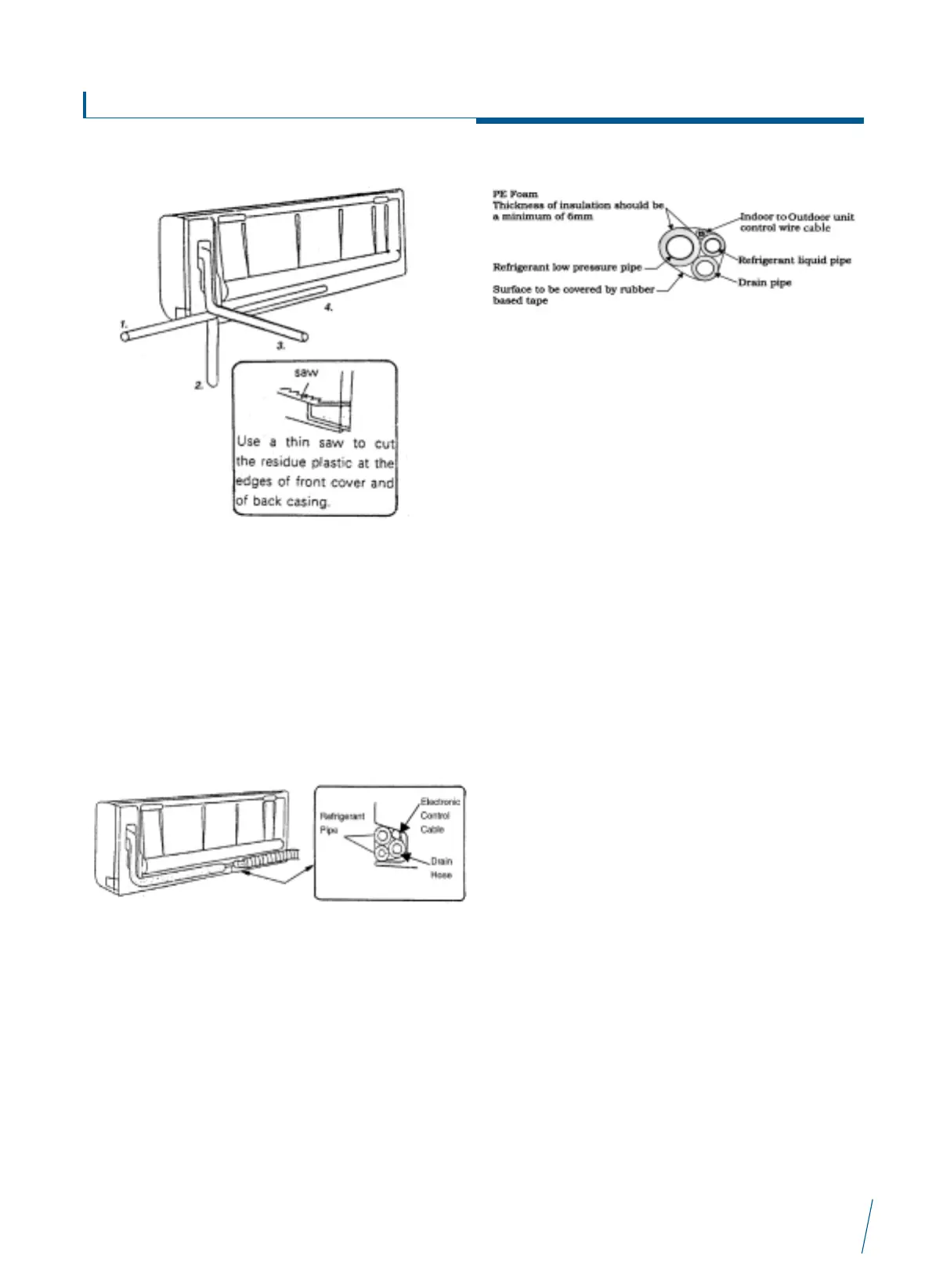
1. As shown in the drawing, there are four alternative directions
for connecting pipe.
2. Please note when alternative 1, 2 or 4 connecting direction is
selected, the residue plastic at the edges of front cover and
back casing should be cut neatly. These plastic residue can
be kept and re-used when you want to install the unit at
another place.
Horizontal piping connection
1. Before securing the mounting plate all the piping should be
connected and wrapped with PVC tape for protection.
2. After connecting all wires place them inside the pipe and
draw the cable through the knock out hole, then secure the
unit on the mounting plate.
3. Apply insulation to the indoor unit’s drain pipe if it is
extended.
Piping insulation method a for heat pumps
Drain pipe should be placed below the refrigerant piping
Interconnecting wiring
We recommend that screened cable be used in electrically noisy
areas.
1. Always separate low voltage (5VDC) signal wires from power
line (230VAC) to avoid electromagnetic disturbance of
control system.
2. Do not install the unit where electromagnetic waves are
directly radiated at the infra red receiver on the unit.
3. Install the unit and components as far away as is practical
(at least five meters) from the electromagnetic wave source.
4. Where electromagnetic waves exist use shielded sensor
cable.
5. Install a noise filter if any harmful noise exists in the power
supply.
Interklima High wall unit
II/IO - SCV1
15