Interklima High wall unit
II/IO - SCV1
34
6.
Before performing recommended maintenance, be sure the unit
main power switch is turned off. Failure to do so may result in an
electric shock or injury from the rotating fan blade.
SERVICE (PACK) VALVES - The service valves in the condensing
unit come from the factory closed. This means the refrigerant
charge is isolated from the line side of the connection ports. The
service valves must be opened (turned counter clockwise until
seated) before the service port caps can be removed and the
hoses of the gauge manifold connected. In this position, the
refrigerant has access from and through the outdoor and indoor
unit. The service valves can not be field repaired.
PUMP-DOWN PROCEDURE - The system may be pumped down
in order to make repairs on the low side without losing the
complete refrigerant charge.
1. Attach a pressure gauge to suction service valve gauge port.
2. Frontseat (close) the liquid line valve.
3. Start unit and run until suction pressure reaches 35 Kpa.
4. Shut unit off and frontseat (close) suction valve.
5. Vent remaining pressure.
TABLE 1: CHARGING TABLE
SERVICE (PACK) VALVES - see liquid and suction valve as shown
in fig. 3&4 - The service valves in the condensing unit come from
the factory closed. This means the refrigerant charge is isolated
from the line side of the connection ports.
The service valves must be open (turned counter clockwise until
seated) before the service port caps can be removed and the hoses
of the gauge manifold connected. In this position, the refrigerant has
access from and through the outdoor and indoor unit. The service
valves cannot be field repaired, there fore only a completed valve or
valve system and service caps are available for replacement.
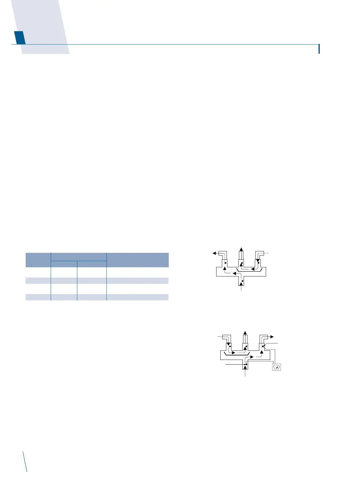
REVERSING VALVE- In heat pumps, the change over between
heating and cooling modes is accomplished with a valve that
reverses the flow of refrigerant in the system. The reversing valve
solenoid can be checked when the power is off with an ohm
meter. Check for continuity and shorting to ground. With the
control circuit (230V) power on, check for the correct voltage at
the solenoid coil. Check for a burned or overheated solenoid. With
the unit operating, other items can be checked, such as frost or
condensate water on the refrigerant lines.
Using a remote measuring device, check the inlet and outlet line
temperatures. Do not touch the lines. if the reversing valve is
operating normally, the inlet and outlet temperatures on the
appropriate lines should be close. Any difference would be due to
heat loss or gain across the valve body. Temperatures are best
checked with a remote reading electronic type thermometer with
multiple probes.
Figures 3 and 4 show test points (tp) on the reversing valve for
recording temperatures. Insulate points for a more accurate
reading. If the valve is defective; shut off all power to the unit and
remove all charge from the system. Remove the valve using a
tubing cutter. Wrap the new valve with a wet rag to prevent over
heating while brazing.
REVERSING VALVE IS ENERGISED WHEN CHANGING FROM
COOL TO HEAT MODE OR FROM HEAT TO DEFROST MODE
After the valve is brazed in, check for leaks, evacuate and charge
system. Operate the system in both heat and cool modes several
times to be sure the valve functions properly.
Service
PACK VALVE SYSTEM CHARGE (kg)
MODEL GAS LIQUID IO (R-410A)
II-09 3 / 8" 1 / 4" 0.98
II-12 1 / 2" 1 / 4" 1.10
II-18 1 / 4" 1 / 4" 1.30
II-22 5 / 8" 3 / 8" 1.65
 Loading...