2 / 48 P/N MAINST-ATS111x (ML) • REV D • ISS 24JUN14
EN: Installation Sheet
Mounting the unit
The RAS cover is hinged at the bottom. To open, grasp the
cover at the sides or the top and pull gently — the cover will
swing down on its pins. The cover may be fully removed by
gently prising one of the pins away from the body of the RAS
and pulling. A locking screw holds the metal mounting plate at
the rear. To remove the metal mounting plate, loosen the
screw by at least 8 mm (0.315 in.), sliding the mounting plate
down, and then pulling the bottom of the mounting plate away
from the body of the RAS.
Attach the metal mounting plate to mounting surface using the
three screws provided. If rear cable entry is used (through the
mounting plate), cut a hole in the mounting surface for cable
access. Set the RAS address using DIP switches 1 through 4
(see “RAS DIP switch settings” below). Set the bus termination
switch (DIP switch 5), if required. Terminate the bus cabling.
WARNING: All power should be turned off to the control panel
before wiring the RAS.
Insert plastic cable entry blanking plugs (provided) into the rear
of the RAS to blank any unused cable entry channels. Place
the RAS onto the mounting plate and lock in place by moving
the unit down by about 8 mm (0.315 in.) Tighten the locking
screw at the base of the RAS till firm. Do not over-tighten.
Figure 2
1. Cable entry
2. DIP switches
3. LAN terminals
4. Tamper switch
5. Locking screw
Connecting control panel to keypad
Refer to the ATS control panel installation guide for
instructions.
Tamper switch
See figure 2.
The rear tamper switch must be sealed for the system to work
correctly. The tamper switch is sealed by mounting the RAS
onto the mounting plate, and then moving it to the locked
position. In operation, the LCD display will show “RAS Tamper”
when not sealed.
RAS DIP switch settings
See figure 3.
A row of DIP switches is located on the rear of the RAS
(figure 2) and is used for setting the RAS address and the bus
termination (TERM) condition. These settings are described in
the following sections.
• TERM switch: Use switch 5 to set TERM to On, if needed.
There must be no more than two TERM switches or links
set to On for any bus. Refer to the control panel
installation guide for details about the use of TERM
switches or links.
• RAS address: Set the RAS address using switches 1 to 4.
Connections
See figure 4.
• +13.8 VDC: The RAS can be powered using the bus “+”
and “−” power from the control panel, if the distance
between the RAS and the control panel does not exceed
100 m (328 ft.) Otherwise the RAS can be powered by
AUX PWR from a DGP, or by an auxiliary power supply.
• D+/D−: D+ is the data positive connection and D− is the
data negative connection of the data bus.
The RAS is connected to the ATS panel via the RS485 data
bus, up to 1.5 km from the control panel or the four-door
controller DGP. It is recommended to use two-pair twisted,
shielded data cable (WCAT 52/54). The shield of any bus
cable must be connected to system ground at one end only.
The ATS111x RAS is not provided with an Earth connection for
this purpose. If the bus is daisy-chained to the RAS, ensure
that the shield of the cable is jointed to provide continuity of
data cable shield.
• RTE: An RTE button (normally open, momentary push-
button switch) can be connected across the “IN” and “0 V”
terminals (see figure 4). When pressed, the button
controls the request to exit function to the panel.
• IN: A request to exit button (normally open, momentary
push-button switch) can be connected across “IN” and “−”.
When pressed, this button controls the request to exit
function.
• OUT: Open collector output. Use the first output number of
the output controller assigned to the RAS. Refer to the
ATS control panel programming manual for details.
Note: When using IN or OUT pins, it is recommended to use a
shielded cable (WS104). Ensure that the shield of the cable is
connected to ground at one end only.
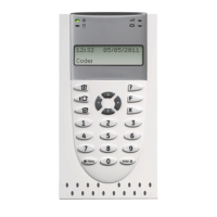
Status LED indications
See figure 1.
Green: The Power LED is on when the control panel
is powered by the AC supply.
Yellow: The Fault LED illuminates to indicate
detection of a system fault.
Blue: The Access LED flashes when access to an
area assigned to the RAS is granted.
Red: The Alarm LED illuminates when there is a
system tamper or an area assigned to the RAS is in
alarm state. The area may be identified by viewing
the 16 area LEDs visible when the RAS cover is
open or removed.
Area LED indications
See figure 1.
When the RAS cover is open or removed, 16 red LEDs are
visible at the bottom of the RAS. Each LED represents an
area, and the indications are as follows:
• The LED illuminates when its corresponding area is
armed.
• The LED flashes slowly when a fault is detected or when
an alarm occurs, in disarmed state.
 Loading...