6 / 7 P/N 466-5444 • REV A • 8NOV18
Fail Safe/F ail Secure Modes
The lock relay operates in the failsafe mode (factory default)
when the lock relay state during alarm is the same state as
when the unit is not powered. During the power up period,
the relay will be in the same state as during normal
unalarmed operation. The lock relay operates in the fail
secure mode where the lock relay state during normal
unalarmed operation is the same as when the unit is not
powered. During the power up period, the relay will be in the
same state as during the alarm period.
Note: The fail secure mode must be authorized by your local
authority. Listed panic hardware shall be used to allow
emergency exit from the protected area.
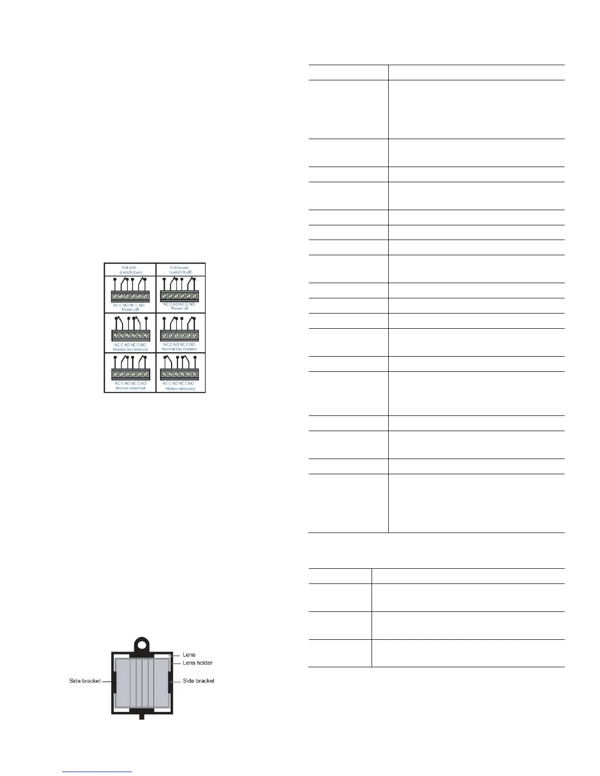
Figure 14 shows the fail safe and fail secure modes relay
contacts.
Figure 14: Fail Safe/Fail Secure Modes Relay Contacts
Mask Installation
The RCR-REX has a mask included that allows you to adjust
the PIR field of view. This may be necessary for some
installations when the unit may be tripped by non-exiting foot
traffic or other erroneous sources that are with the detection
area.
To install the mask, do the following:
1. Remove the appropriate segments of the mask to
include the desired area of detection.
2. Open the RCR-REX cover and locate the PIR lens.
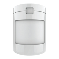
3. Slip the mask into the two side brackets that hold the
PIR lens in place (Figure 15). Be careful not to dislodge
the lens.
4. Close the cover.
Figure 15: Mask installation
Specification
23mA typical, 27mA maximum at 12 VDC
15mA typical, 17mA maximum at 24 VDC
31mA typical, 38mA maximum at 12 VAC
26mA typical, 29mA maximum at 24 VAC
1/2, 1, 2, 4, 8, 16, 32, 64 seconds ± 10%,
selectable
AWG 14 to 22 (18 to 22 recommended)
-20 to 122°F (-29 to 50°C)
20V/meter from 80 MHz to 1 GHz
3 to 15 ft. (0.9 to 4.57 m)
7.9 ft. (2.4 m)
7 to 15 ft. (2.13 to 4.57 m) typical
7.4" x 1.76" x 1.85"
(187.8 x 44.7 x 47 mm)
C UL-US
Industry Canada
CE (pending)
FCC
Product Ordering
RCR-REX request-to-exit dual technology
motion sensor, off-white
RCR-REX request-to-exit dual technology
motion sensor, black
RCR-REX request-to-exit dual technology
motion sensor, gray
Note: The equipment should be installed in accordance with the
National Electrical Code, ANSI / NFPA70.