2 / 3 P/N 466-2912 • REV A • ISS 05JAN17
3
4
EN: Installation Sheet
Wiring diagram
Figure 2 legend
(1) Siren PCB
(2) Speaker
(3) Beacon
(4) 4X lithium battery pack (not included)
(5) IO module power cable (black)
(6) Tamper
(7) Tamper
(8) Beacon + (red)
(9) Beacon- (black)
(10) Siren driver + (red)
(11) Siren driver − (black)
(12) IO module PCB
Learning-in an outdoor siren
You have to learn-in the siren before mounting it to the desired
position. In order to add a wireless siren to the system perform
the following steps:
1. Enter the programming mode on the panel
2. Enter your username and password and then click Sign In.
3. Click Settings.
4. Click Zones.
5. The outdoor siren will occupy maximum 4 zone numbers.
Click “Select Zone to Configure” to set the first zone
number of the outdoor siren.
6. Click Learn.
7. Power up the outdoor siren with the tamper switch open.
8. Wait for module LEDs to blink on, then off.
9. Close tamper switch for 2 seconds, then reopen within 5
seconds.
10. The screen will indicate the outdoor siren has been
learnt-in and a serial number will appear. Read the pop up
messages.
11. Select Outdoor Siren as the application.
12. Click Save when done.
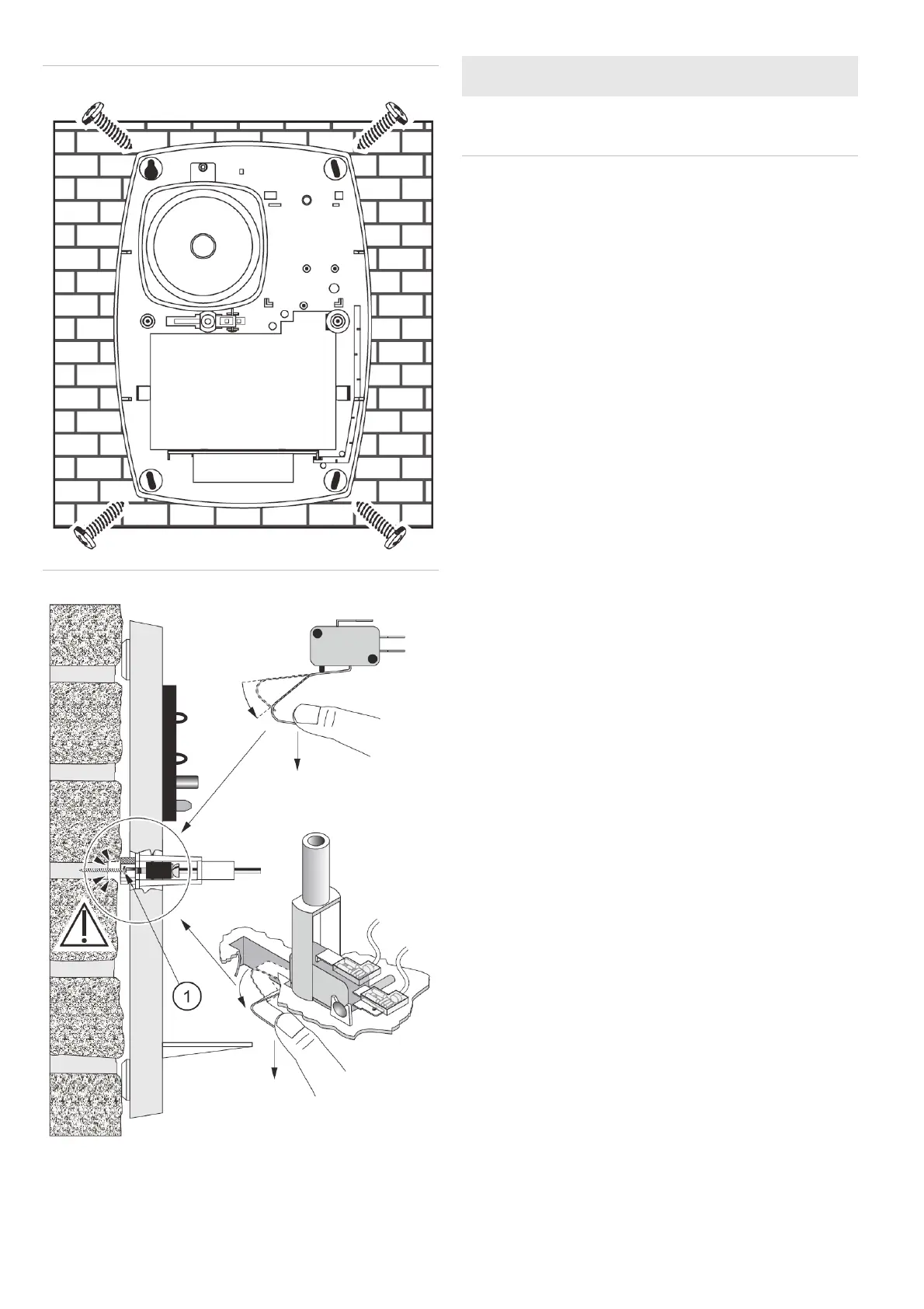
Mounting the siren
For mounting instructions, see Figure 3. Pay attention to the
precise placement of the tamper switch against the wall. To
comply with an EN50131-4 grade 2 installation, please take
special care of positioning the tamper switch lever to the wall,
and insert a screw in the wall opposite to the tamper switch
lever. This screw has to be adjusted in height in order to press
adequately on the tamper switch lever so that the microswitch
is in a “closed” position and resting on the screw’s head
instead of the wall (see Figure 4, position 1). The siren needs
to signal a tamper alarm when the unit is taken more than
5 mm from its mounting surface (see Figure 4).
Siren configuration
To allow the IO module to control the output on the outdoor
siren, you need to cut jumper 3 and then optionally 1 and/or 2.
Jumper 3 is a start-up protection. Jumpers 1 and 2 are
responsible for timer settings, and you can cut one of them or
both, according to the table below.