EasyManua.ls Logo

Intermatic EJ600 Series - User Manual

Intermatic EJ600 Series
12 pages
Print Icon
To Next Page IconTo Next Page
Loading...
7. Using diagram #2 remove and reconnect wires “B” and “C” to
the “COMMON” terminal of your remote switch, using the
supplied piece of jumper wire, if necessary.
NOTE: For new construction or to replace a dimmer switch, a
lighted switch, or a 3-way switch without screw terminals, a
single-pole switch should be used at the remote location, as
shown in diagram 3.
NOTE: If the building’s wiring colors don’t allow you to tell wire “A”
from “B”, just pick one of the two wires and connect as if it is wire “B”.
After the installation is complete, if the controlled light or device will
not turn on properly, simply reverse wires “A” and “B”. See Steps 11
through 14 below for how to check.
8. Gently tuck wires into the timer wall box leaving room for the timer.
9. Using screws provided, mount the switch timer into the wall
box, then install the wall plate.
10. Turn the power back on at the service panel.
11. Make sure the switch timer displays “MAN” mode. Perform the
test in Step 12 with the remote switch in each of its 2 positions.
12. Press the NEXT/ON/OFF button on the switch timer several
times. Each time that you push the NEXT/ON/OFF button, the
controlled light or device (the “load”) should turn on or off. If so
proceed to Step 14.
13. If the controlled light or device does not turn on or off, take one
of these actions.
- If the timer clicks but the load does not operate, re-check
your wiring and make sure the load is functional.
- If the timer clicks but the load only operates when the remote
switch is in one of its 2 positions, you need to turn off the
power at the service panel, then reverse wires “A” and “B”.
You can reverse wires “A” and “B” at the remote switch wall
box, or you can reverse wires “A” and “B” where they
connect to the red and blue wires of the switch timer. Then
turn power back on at the service panel and repeat Step 12.
14. Verify that the controlled load turns on or off each time that the
remote switch is operated. Your timer is ready to be set.
15. Proceed to Intro to Programming.
Installing the Switch Timer
1. Turn off power at the circuit breaker or fuse and verify that the
power is OFF before wiring.
2. Strip wire ends to 7/16”.
3. Make wire connections using the twist on
connectors provided.
4. Take one of these actions.
- If you have a single switch setup, then perform the
procedure “Installing the Timer with a Single Switch Setup”.
- If you have a 3-way switch setup, then perform the
procedure “Installing the Timer with a 3-way Switch Setup”.
Installing Switch Timer with a Single Switch Setup
1. Connect the LINE (Hot) wire from the wall to the black wire
from the switch timer with the twist
connectors provided.
2. Connect the LOAD wire from the wall to
the blue wire from the switch timer with
the twist connectors provided.
3. NOTE: Cap the RED wire, which is
not used in single-switch installations,
with a twist connector.
4. Connect the BARE COPPER wire
to the grounding screw in the box
If a plastic box, connect to ground as supplied.
5. Connect the NEUTRAL (usually White) wire from the wall to the
WHITE wire from the timer.
6. Gently tuck wires into the timer wall box leaving room for the timer.
7. Using screws provided, mount the switch timer into the wall
box, then install the wall plate.
8. Turn the power back on at the service panel.
9. Go to “Intro to Programming: Read Before you Begin.”
Installing the Timer with a 3-Way Switch Setup
NOTE:
The distance between switch timer and
remote switch must not exceed 100 feet.
The timer must be installed in the wall box
that contains the LINE and Neutral
wires. The remote switch must be
installed in the wall box that contains
the load wire (“WIRE C” in diagram 1).
1. Using diagram #1 below, identify the
LINE wire previously connected to the COMMON terminal of
the old 3-way main switch.
2. Connect the BLACK wire from switch timer to the LINE wire,
using a twist connector.
3. Connect the other two wires from the old switch to the BLUE
and RED wires from the switch timer.
4. Connect the BARE COPPER wire to the grounding screw in the
box. If a plastic box, connect to ground as supplied.
5. Connect the NEUTRAL (usually White) wire from the wall to the
WHITE wire from the timer.
6. Using diagram #1 below, identify and remove wire “C” from the
“COMMON” terminal of your existing remote switch.
7/16”
DIAGRAM 1:
TYPICAL
EXISTING
2-SWITCH
SETUP
LOAD
NEUTRAL
3-WAY
MAIN SWITCH
WIRE “A
“COMMON TERMINAL
LINE
3-WAY
REMOTE SWITCH
WIRE “B”
WIRE “C”
DIAGRAM 2:
2-SWITCH SETUP,
TIMER INSTALL
RE-USING EXISTING
REMOTE 3-WAY SWITCH
LOAD
NEUTRAL
WIRE “A
“COMMON” TERMINAL
LINE
3-WAY
REMOTE SWITCH
WIRE “B”
NOT USED
BLACK
TIMER
BLUE
RED
WIRE “C”
JUMPER
NEUTRAL
WHITE
DIAGRAM 3:
2-SWITCH SETUP,
TIMER INSTALL USING
NEW SINGLE-POLE
REMOTE SWITCH
LOAD
NEUTRAL
WIRE “A”
LINE
SINGLE-POLE
REMOTE SWITCH
WIRE “B”
BLACK
TIMER
BLUE
RED
WIRE “C”
JUMPER
NEUTRAL
WHITE
BLACK
BLUE
RED
(capped, not connected)
WHITE
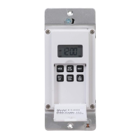
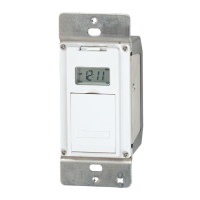
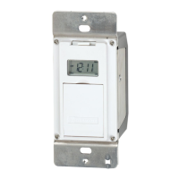
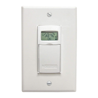
DIGITAL ASTRONOMIC TIMER
MODEL EJ600 SERIES
Installation and User Instructions
RATINGS:
Single or multiple gang installations
Resistive 12 A
Tungsten 15 A (1800 W) Single Ganged, min 18 in
3
(295 cm
3
)
14 A, Single Ganged, minimum 12.5 in
3
(205 cm
3
)
12 A (1440 W) Multi-Ganged
Ballast 500 VA
Motor - 1/2 Hp
All ratings 120 VAC, 60 Hz.
A Neutral (WHITE) wire must be available to connect to timer.
BLACK
BLUE
RED
WHITE
WARNING
Risk of Fire or Electrical Shock
Disconnect power at the circuit breaker(s) or disconnect switch(es) before
installing or servicing.
Do NOT recharge, disassemble, heat above 100˚C (212˚F), crush, or incinerate the
non-replaceable Lithium battery. Keep out of reach of children.
Do NOT use timer to control devices that could have dangerous consequences due
to inaccurate timing such as sun lamps, sauna, heaters and crock pots.
Use #14 AWG wires, rated at least 90°C (194°F) - COPPER conductors ONLY.
Installation and/or wiring must be in accordance with national and local electrical
code requirements.

Other manuals for Intermatic EJ600 Series

Questions and Answers

  • R
    robinmanningAug 16, 2025
    What to do if Intermatic EJ600 Timer is blank and light flickers?
    • T
      Tara HuertaAug 16, 2025
      If your Intermatic Timer display is blank until a button is pushed, and the display changes between ON and OFF when pressing the door, but the light stays OFF or flickers, it could be due to no power (blown fuse or circuit breaker), a loose wiring connection, or no load/burned-out bulbs. Ensure the fuse is not blown and the circuit breaker is on. Replace the fuse if necessary.
  • A
    allenaliciaAug 18, 2025
    Why Intermatic EJ600 does not switch but display is normal?
    • V
      Vanessa FischerAug 18, 2025
      If your Intermatic Timer display is normal, but it is not switching, it is likely not in AUTO, AUTO RAND(om), or MAN(ual) mode. Press the MODE button to select the desired operating mode.
  • A
    Angela BlairAug 22, 2025
    What to do if Intermatic EJ600 works manually but does not follow scheduled program?
    • F
      Frank BaileyAug 22, 2025
      If your Intermatic Timer works manually but does not follow the scheduled program, it is likely not in AUTO or AUTO RAND(om) mode. Press MODE to select AUTO RAND.
  • K
    Kevin WoodAug 25, 2025
    Why Intermatic EJ600 Timer will not enter the AUTO or AUTO RAND modes?
    • C
      Christina ThompsonAug 26, 2025
      If your Intermatic Timer will not enter the AUTO or AUTO RAND modes when MODE is pressed, it may be because the time of day and/or switching times are not programmed. Make sure the time of day and at least one scheduled activity are programmed.
  • J
    Jennifer CookAug 27, 2025
    What to do if Intermatic EJ600 Timer switches at incorrect times?
    • G
      Gregory HicksAug 27, 2025
      If your Intermatic Timer switches at incorrect times or skips some switching times, it is likely that the programmed schedules are incorrect. Review ALL 7 ON/OFF switching time pairs by repeatedly pushing NEXT ON/OFF while in PGM mode and revise as necessary.
  • P
    pjacksonAug 30, 2025
    How to exit AUTO RAND(om) mode on Intermatic EJ600?
    • C
      Corey ReedAug 31, 2025
      To exit the AUTO RAND(om) mode on your Intermatic Timer, press the MODE button to select AUTO mode.
  • I
    Isabella MarquezSep 2, 2025
    What to do if Intermatic EJ600 load state does not match programmed state?
    • M
      Mary AlexanderSep 3, 2025
      If the load state of your Intermatic Timer does not match the programmed state immediately after programming the time or schedule, it is because the timer does not “catch up” to the programmed load state. After entering your schedule or the time, then returning to the AUTO modes, push NEXT/ON/OFF to change the load state if necessary.
  • D
    Dawn LucasSep 5, 2025
    Why Intermatic EJ600 load only operates in one remote switch position?
    • D
      drodriguezSep 5, 2025
      If the load of your Intermatic Timer only operates when the remote (3-way) switch is in one position, or the timer ignores the remote switch, the remote switch may be wired incorrectly. Verify the wiring is installed correctly, including the jumper.
  • M
    millernathanielSep 9, 2025
    What causes Intermatic EJ600 Timer to ignore remote switch?
    • T
      tracy97Sep 9, 2025
      If your Intermatic Timer ignores the remote (3-way) switch even though it is wired correctly, it could be due to excessive wire length (greater than 100 feet) or buried wiring to the remote switch. You can eliminate this condition by replacing the buried cable or doing without the remote switch. Another cause could be a defective or worn-out remote switch, in which case you should replace the remote switch.
  • U
    ubrownSep 12, 2025
    Why does the load turn off immediately after being turned on with Intermatic Timer?
    • T
      Tonya NewmanSep 12, 2025
      If the load turns off immediately after being turned on with your Intermatic Timer, it could be due to the remote switch or timer being wired incorrectly, excessive wire length (greater than 100 feet) or buried wiring to the remote switch, or a defective timer. If the problem persists with the timer’s red wire disconnected or with a remote switch temporarily connected right at the timer, replace the defective timer. Otherwise, try the above remedies.

Summary

Installation and User Instructions

General Safety Warnings

Important safety precautions for installation and use of the timer.

Single Switch Setup Installation

Procedure for installing the timer with a single switch.

3-Way Switch Setup Installation

Procedure for installing the timer with a 3-way switch.

Programming the Timer

Setting Calendar Information

Procedure to set calendar for seasonal and DST adjustments.

Setting Time of Day

Procedure to set the current time and date.

Setting Specific ON;OFF Programs

Configuring scheduled on and off times for the load.

Setting Sunrise;Sunset Programs

Configuring ON/OFF times based on sunrise and sunset.

Reviewing and Revising Programs

How to check and modify existing program settings.

Selecting Operating Modes

Choosing between AUTO, AUTO RANDOM, and MANUAL modes.

Battery Memory Backup Details

Information on the rechargeable battery backup.

Manual Override Function

How to temporarily override programmed times.

Troubleshooting Guide

Limited One-Year Warranty

Intermatic EJ600 Series Specifications

General IconGeneral
Frequency60 Hz
Battery BackupYes
BrandIntermatic
CategoryTimer
Horsepower1/4 HP
Number of Poles1
Minimum Time Setting1 Minute
ColorWhite
Number of Circuits1
TypeElectronic Timer
Voltage120 VAC
Amperage15A
Timing Range24 Hour
Maximum Time Setting23 Hours, 59 Minutes
MountingWall Mount
Load RatingResistive, Ballast
Timer TypeElectronic
Clock Accuracy+/- 1 Minute per Month

Related product manuals