AM ON
5
5
:
:
2
2
0
0
10. Press the reset switch for three to five seconds. The
display will now show 12:00 A.M. and Event #1. The
timer is now ready for programming. Refer to the chart
below and enter the scheduled events (set points)
required.
EVENT TIME
On 1
Off 2
On 3
Off 4
On 5
Off 6
On 7
Off 8
Programming Steps
Refer to programming instructions on time switch door
label and note the following:
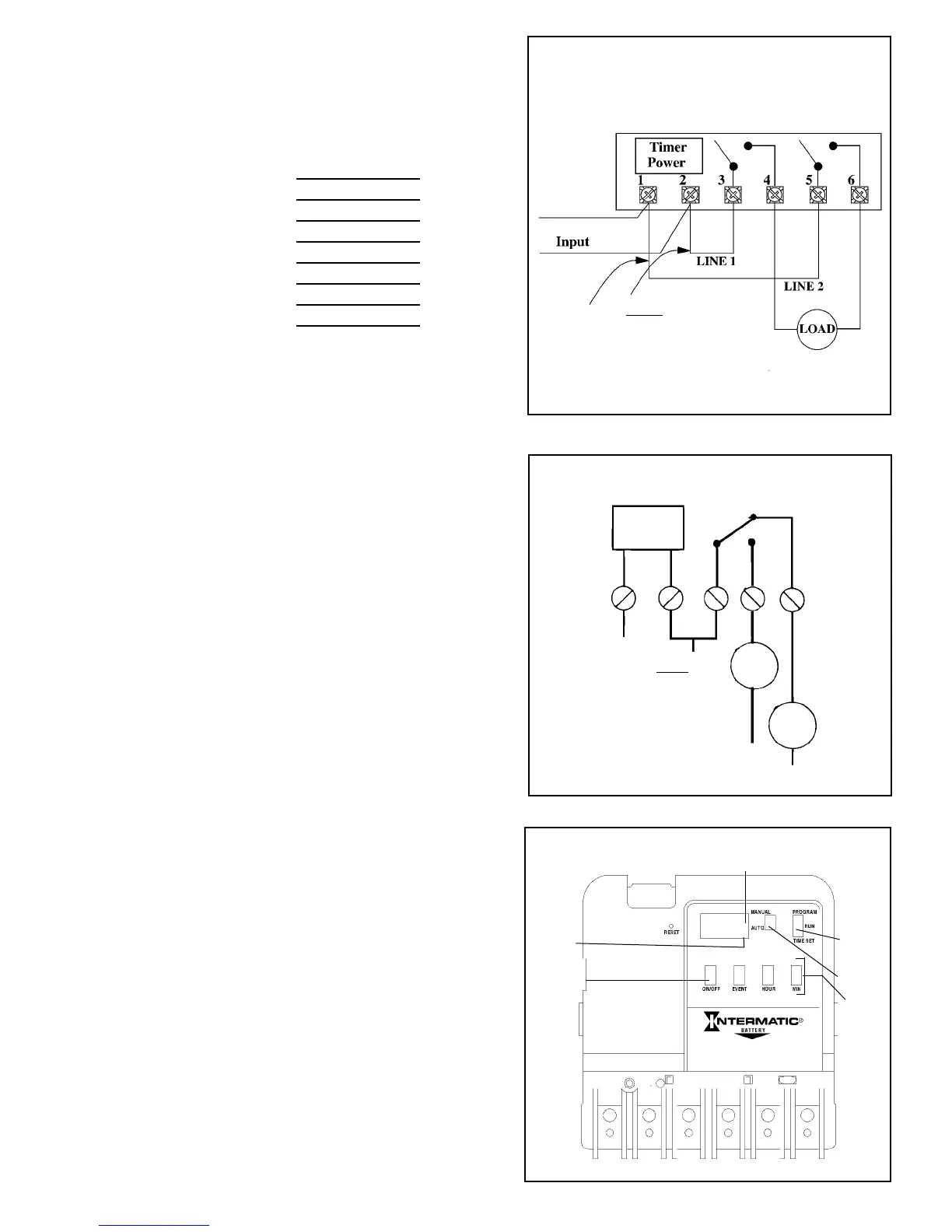
• The MANUAL/AUTO selector can be used to temporarily
override the program. Under normal operation the
selector should be in the AUTO mode. The MANUAL
mode maintains the program but prevents the loads
from automatically switching.
• The other selector switch is used to set the time of day
(TIME SET), the program information (PROGRAM) or to
run the program (RUN). FOR A PROGRAM TO
FUNCTION PROPERLY, THE TWO SELECTOR
SWITCHES MUST BE IN THE AUTO AND RUN
POSITIONS.
• The RESET switch is used only prior to initially programming
the time switch or to erase all programmed set points.
• By holding the hour and/or minute buttons depressed
you can achieve a fast roll of the displayed time. This is
useful when setting the time of day or setting the
programmed set points (events).
• Up to 4 ON and 4 OFF set points (8 events) can be
programmed.
• The load can manually be switched ON or OFF at any
time only if the selector switch is in the RUN mode by
pressing the ON/OFF button.
• Pressing the ON/OFF button two times in the
PROGRAM mode causes the event time displayed to be
removed from the program. The display will show 0:00
and the Event (1 through 8).
To Operate Timer
After programming is complete, move the selector
switches to the RUN and AUTO positions. The time switch
will follow the scheduled program but will not immediately
“catch up” to the presently programmed load condition; the
time switch will “catch up” at the next scheduled ON or
OFF setpoint. If necessary, press the ON/OFF button to
turn the load on or off.
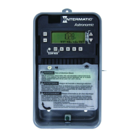
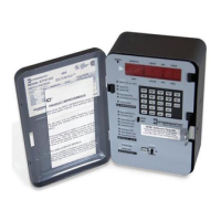
FIG. #4
ET103C DPST
LOAD STATUS INDICATOR
“ON” or “OFF”
EVENT
INDICATOR
PROGRAMMING
BUTTONS
MANUAL/AUTO
SELECTOR
PROGRAM
SELECTOR
PROGRAMMING/
MANUAL LOAD
CONTROL
BUTTON
FIG. #6
Install Jumper Only If Timer
Input and Load Voltage Are
The Same, Otherwise provide
a separate source of load
power to terminal 3& 5.
120 VAC
Neutral
Hot
NOTE: For 120 Volt loads only since the timer voltage is 120 VAC
a jumper can be added between terminals 2, 3 and 5 to supply load
power.
CAUTION: Do not use jumper if load(s) are not 120V. because the
load can be damaged. Supply separate power of the correct voltage to
terminal 3 and 5.
NOTE: For 120 Volt loads only since the timer voltage is 120 VAC
jumpers can be added between terminals 2 and 3 to supply load power.
CAUTION: Do not use jumpers if load(s) are not 120V. because the load can be
damaged. Supply separate power of the correct voltage.
TIMER
POWER
1
2
34
LOAD 1
5
LOAD 2
NEUTRAL
LINE
LINE 1
Install jumper Only If Timer
Input and Load Voltage Are
The Same, Otherwise provide
a separate source of load
power to terminal 3.
For breaking one side of
120 volt loads.
FIG. #5
ET105C SPDT