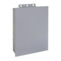
Mounttheenclosureinthedesiredlocationusingthe3mount-5.
ingholesprovided.
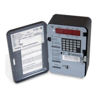
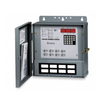
Position at eye level if possible, providing space to the left of
the enclosure for the cover to swing open fully, as shown.
Replacethemechanismintheenclosure.6.
Lifttheleftsideoftheplasticinsulatorofftheretainingpostand7.
pivotitupandawaytoexposetheterminalstrip.
Stripthesupplyandloadwiresto1/2”.8.
Use AWG#10-#18 copper conductors only.
1
Neutral
120VAC
Input
Hot
2 3 4
Timer Power
Load
Install jumper
only if timer input
and load voltage
are the same
ET8015 configured for SPST, 120 VAC load
1
Line 2
120/208/240/277
VAC Input
Line 1
2 3 4 5 6
Load
1
Load
2
Timer Power
Install jumper only if timer input
and load voltage are the same
ET8115 configured for SPDT load switching
1
Line 2
240VAC Input
Line 1
2 3 4 5 6
Line 1
Line 2
Install jumper only if timer input
and load voltage are the same
Timer Power
Load
ET8215 configured for 240VAC DPST load
with jumper set to SIM
1
Line 2
120/208/240/277
VAC Input
Line 1
2 3 4 5 6
ON
Install jumper only if timer input
and load voltage are the same
OFF
Timer Power
ET8215 configured for pulse SPST load
with jumper set to PUL
1
Line 2
120/208/240/277
VAC Input
Line 1
2 3 4 5 6
Load
1
Timer Power
Load
2
ET8215 configured for 2 SPST loads
with jumper set to IND
1
Line 2
120/208/240/277
VAC Input
Line 1
2 3 4 5 6
Load
1
Timer Power
Load
2
ET8215 configured for DPST loads
with jumper set to SIM
Mounting
Holes
Knockouts
Mounting
Hole
Insertthewireendsundertheproperterminalplates(seewir-9.
ingdiagramselsewhereonthispage)andtightenthescrews
rmly.
Connectgroundwiretogroundingterminalatbottomofenclosure.10.
Replacetheplasticinsulatorontheretainingpost.11.
Removethebatterycasebyslidingitdownasshownbythe12.
arrows,theninstall2AAAalkalinebatteries.Makesurethe
batteriesarepointinginthedirectionshown.
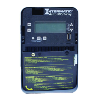
Verifythatthedisplayis13. ONtomakesurethebatteriesareOK.
If the display shows scrambled information, press the RESET
button to clear it up.
ApplypowertotheTimeSwitch.14.
IMPORTANT: 15. PressandholdtheENTERbutton,thenpressthe
RESETbutton.Thescreenwillash12:00AMandMON,and
timerstatusisManualMode.
NOTE: You must reset the time switch using this procedure
whenever you change the jumpers.
The Time Switch is now ready for programming.
Programming Overview
BypressingtheMODEbutton,theTimeSwitchwillcyclethroughthe
menusnecessaryforprogrammingthecurrenttime,date,astrozone,
astroevents,andtimedevents.
ThebasicprocedureistousetheMODEbuttontomovefromone
menutothenext(e.g.,DATE,TIME,etc.),the+ or – buttonsforthe
rstpartofasetting(e.g.,MONTH),theENTERbuttontomoveto
thenextpartofthesetting(e.g.,YEAR),thenMODEtoexitandmove
tothenextmenu.Toskipamenu,pressMODEtomoveahead.
If you make a mistake, press the MODE button repeatedly to cycle
back around to the error, then make the correct entry.
NOTE: DATE and TIME must be set before you can access any
other programming menus.
1 – Setting Date
Pressthe1. MODEbuttonrepeatedlyuntilthewordsSETand
DATEappearintheupperareaofthedisplay.
2 – Setting Time
Ifnecessary,pressthe1. MODEbuttonrepeatedlyuntilthewords
SETandCLOCKappearintheupperareaofthedisplay.
Pressthe2. + or – buttonstoenterthecurrenttime.
NOTE: To go from AM to PM, keep pressing the + or – but-
tons to cycle through the day. You can hold the + or – but-
tons down for 3 seconds to make the time scroll quickly.
Pressthe3. MODEbuttontoexitandadvancetosettingAstroZone.
Pressthe2. + or –buttonstoenterthecurrentMonth.
Pressthe3. ENTERbuttonwhentheMonthiscorrecttosavethe
setting.ThescreenadvancestocurrentDate.
Againpressthe4. + or – buttonstoenterthecurrentDate,fol-
lowedbytheENTERbutton.
RepeattosetthecorrectYear.5.
Pressthe6. MODEbuttontoexitandadvancetosettingthetime.
Wiring Diagrams

 Loading...