Do you have a question about the Intermatic GRASSLIN FM1D14 Series and is the answer not in the manual?
One circuit electronic 24-hour or 7-day time switches for various electrical loads.
Time-based control for lighting, ventilation, heating, cooling in commercial and industrial applications.
Critical warnings regarding risk of fire or electric shock during installation.
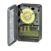
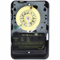
Procedure for attaching the FM1D14A model to a surface or DIN rail.
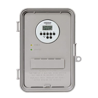
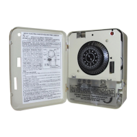
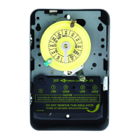
Instructions for installing the FM1D14E model into a panel opening.
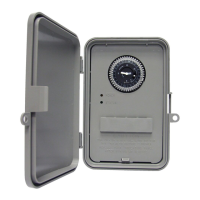
The Grasslin FM1D14 Series is a range of single-circuit electronic time switches designed for precise control of electrical loads in commercial and industrial settings. These devices offer flexible programming for either 24-hour or 7-day schedules, making them suitable for a wide array of applications such as managing lighting, ventilation systems, heating, and cooling equipment. The series includes two primary models: the FM1D14A, designed for surface or DIN rail mounting, and the FM1D14E, intended for flush (panel) mounting. Both models are supplied with a clear plastic dust cover to protect the internal components.
At its core, the FM1D14 Series time switch acts as a programmable controller that automates the switching on and off of electrical circuits based on a user-defined schedule. This automation capability is crucial for energy efficiency and operational convenience, allowing users to set specific times for various electrical loads to operate without manual intervention. The electronic nature of these time switches provides a high degree of accuracy and reliability compared to traditional mechanical timers.
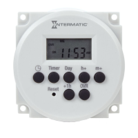
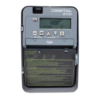
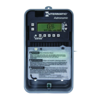
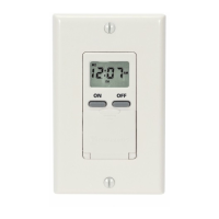
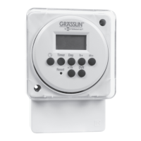
The programming interface, visible on the device's front panel, typically includes buttons for setting the time, day, and specific ON/OFF events. The display provides clear feedback on the current time, day, and program status. Users can define multiple ON/OFF events throughout the day or week, tailoring the operation to specific business hours, occupancy patterns, or environmental needs. For instance, a user might program lights to turn on at dawn and off at dusk, or ventilation systems to operate only during peak business hours. The 24-hour and 7-day scheduling options provide the flexibility to account for different operational requirements on weekdays versus weekends, or to implement recurring daily cycles.
An important feature is the ability to override the programmed schedule. This is often indicated by a "Reset" or "OVR" (Override) button on the front panel. An override function allows for temporary manual control, which can be useful in situations where a deviation from the normal schedule is required, such as during special events, maintenance, or unexpected operational changes. After the override period, the device typically reverts to its programmed schedule, ensuring that long-term automation is maintained.
The internal clock of the FM1D14 Series is designed for accuracy, ensuring that programmed events occur precisely when intended. The electronic circuitry is robust, providing reliable operation over extended periods. The device's ability to handle a single circuit means it controls one specific electrical load or a group of loads connected to that circuit. This makes it ideal for dedicated applications where precise timing of a particular function is critical.
The FM1D14 Series is designed with user-friendliness and installation flexibility in mind.
Mounting Options:
Programming Interface: Both models feature an intuitive front-panel interface with a digital display and control buttons. The display typically shows the current time, day, and programming prompts, making it easy for users to navigate through settings. Buttons are clearly labeled for functions like "Timer," "Day," "h+" (hour increment), "m+" (minute increment), "Reset," and "OVR" (Override). This straightforward design allows for quick and efficient programming of ON/OFF events.
Clear Dust Cover: Both the FM1D14A and FM1D14E models are supplied with a clear plastic dust cover. This cover serves a dual purpose: it protects the display and control buttons from dust, dirt, and accidental damage, and it allows for easy visual inspection of the device's status without needing to open or remove anything.
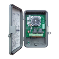
Wiring Connections: The FM1D14E model specifically utilizes 1/4" quick connects for wiring. This type of connector simplifies the wiring process, making it faster and more secure than traditional screw terminals in certain applications. For all models, wiring must comply with national and local electrical code requirements, ensuring safety and proper operation. The manual emphasizes checking input and output ratings to ensure compatibility with the power supply and application.
Application Versatility: The ability to program for 24-hour or 7-day schedules makes these time switches highly adaptable. They can manage daily recurring tasks, such as turning on and off exterior lighting, or more complex weekly schedules, like adjusting HVAC operation based on business days versus weekends. This flexibility is key for optimizing energy consumption and operational efficiency across various commercial and industrial environments.
The Grasslin FM1D14 Series time switches are designed for reliability and minimal maintenance, typical of electronic control devices. However, certain aspects contribute to their longevity and ease of service if needed.
Robust Construction: The devices are housed in durable plastic enclosures, providing protection against environmental factors commonly found in commercial and industrial settings. This robust construction helps to ensure long-term operational integrity.
Clear Dust Cover: As mentioned, the clear plastic dust cover not only protects the controls but also helps to keep the internal components free from dust and debris, which can otherwise accumulate and potentially affect performance or lifespan. This passive maintenance feature reduces the need for frequent cleaning of the control interface.
Modular Design (FM1D14A): For the FM1D14A model, the design allows for the removal of the timer module by pulling it straight out after loosening screws and detaching the housing. This modularity could potentially simplify troubleshooting or replacement of the core timing mechanism if a fault were to occur, without needing to completely dismantle the entire installation. This design consideration can reduce downtime and simplify servicing.
Compliance with Electrical Codes: The emphasis on wiring in accordance with all applicable national and local electrical code requirements is a critical maintenance-related feature. Proper installation, adhering to these codes, ensures that the device operates within safe electrical parameters, minimizing the risk of electrical faults, overheating, or other issues that could lead to premature failure or require extensive repairs. Correct wiring also ensures that the device receives the appropriate power supply, which is vital for its electronic components.
Pre-Installation Checks: The instruction to "check the input and output ratings marked on the unit to make sure this product is suitable for your power supply and application" is a preventative maintenance step. Ensuring compatibility before installation prevents potential damage to the device or the connected load, thereby extending the lifespan of the entire system.
Disconnect Power Warning: The prominent "WARNING Risk of Fire or Electric Shock" and the instruction to "Disconnect power prior to installation" highlight a crucial safety and maintenance protocol. This ensures that any work performed on the device, whether during initial installation or subsequent servicing, is done safely, protecting personnel and preventing damage to the unit from accidental short circuits or power surges during handling.
In summary, the FM1D14 Series time switches are designed to be reliable, easy to install, and user-friendly, with features that contribute to their long-term performance and straightforward maintenance.
| Frequency | 50/60 Hz |
|---|---|
| Programmable | Yes |
| Contact Type | SPDT |
| Number of Poles | 1 |
| Type | Time Switch |
| Display | Digital |
| Operating Temperature | -10°C to 50°C |
| Time Settings | Daily, Weekly |