EasyManua.ls Logo

Intermatic Grasslin GM40 Series - User Manual

Intermatic Grasslin GM40 Series
4 pages
Print Icon
To Next Page IconTo Next Page
Loading...
• Disconnectpoweratthecircuitbreaker(s)ordisconnectswitch(es)beforebeginning
installationorservicing.
• Morethanonecircuitbreakerordisconnectswitchmayberequiredtode-energizethe
equipmentbeforeservicing.
• Donotusethemanualoffpositionofthetimerforequipmentservicing.Alwaysdiscon-
nectthepoweratthecircuitbreaker(s)ordisconnectswitch(es).
• UseCOPPERconductorsONLY.
• For40amploads,use#8AWGwire,rated90˚Cmin.
• Wireinaccordancewithnationalandlocalelectricalcoderequirements.
GM40 Series GeneralPurpose
Multi-VoltageCommercial
DPDTTimeSwitch
WARNING
Risk of Fire or Electric Shock
• Rotatetimerdialclockwiseonly.
CAUTION
Risk of Damage to Timer
1
U.S. Patent #6,563,2371.
UL TYPE 3R Enclosure
MAXIMUM CONTACT RATINGS PER POLE:
N.O. Contacts:
40A Resistive @ 120~277VAC
1HP, 16FLA, 90LRA @ 120VAC
2HP, 12FLA, 52LRA @ 208~277VAC
30A Ballast @ 120VAC
20A Ballast @ 277VAC
15A Tungsten @ 120VAC
300VA Pilot Duty 120~240VAC
N.C. Contacts:
30A Resistive @ 120~277VAC
1HP, 12FLA, 30LRA @ 120VAC
2HP, 10FLA, 30LRA @ 240VAC
2A Tungsten @ 120VAC
10A Ballast @ 277VAC
WIRING CONNECTIONS:
Screw box lug terminals. Up to one #8 AWG
Wire.
ENVIRONMENTAL RATINGS:
Operating Temperature Range:
–40°F to 131°F (–40°C to 55°C)
Operating Humidity: 0 - 95% RH non-condensing
ENCLOSURE DIMENSIONS:
8.795” x 6.631” x 2.935” (H x W x D)
SHIPPING WEIGHT: 3 lbs.
Agency Approvals: UL Listed
INSTALLATION
Note: For outdoor locations, raintight or wet local conduit
hubs that comply with requirements of UL 514B (standard
for fittings for conduit and outlet boxes) must be used.
1. Open door and then remove interior protective
cover by releasing spring clip on bottom.
2. Remove timer mechanism by releasing spring clip
on bottom.
3. Select knockouts to be used. Remove inner 1/2”
knockout by inserting a screwdriver in the slot and
carefully punch knockout loose. Remove slug. If 3/4”
knockout is required, remove the outer ring with pliers
after removing the 1/2” knockout. Smooth edges with
knife if necessary.
4. Place enclosure in desired mounting location and
mark the three mounting holes (refer to diagram).
Start by placing set screw on top and attaching
enclosure over keyhole; then screw in remaining
two screws on bottom.
5. Connect conduit hubs to conduit before connecting the
hubs to the enclosure. After inserting hubs into enclo-
sure, carefully tighten hub lock nut. Do not over-torque.
6. Verify input voltage selection. Refer to DIP switch
diagram for desired input voltage.
7. Wire in accordance with National and Local Codes
(see wiring diagrams).
8. Grounding: Terminate all ground wires to ground
lug on bottom of enclosure.
9. Replace interior protective cover.
ON
ON
ON
ON
120VAC
OFF
OFF
OFF
OFF
277VAC (Default)
OFF
ON
OFF
ON
208~240VAC
INPUT VOLTAGE DIP SWITCH SETTING:
1. Do not apply power to the GM40 prior to setting correct
Input Voltage DIP switch.
2. Determine the input voltage which will be applied to the GM40
(i.e. L1 and L2/N terminals, see wiring diagrams).
3. Set the DIP Switch according to the diagram below.
NOTE:
Unit is shipped with DIP Switches set for 277VAC Input Voltage.
Ground Lug
2-1/2”
6-1/8”
TImer Mechanism
Step 2
Interior
Protective
Cover
Step 1
Question and Answer IconNeed help?

Do you have a question about the Intermatic Grasslin GM40 Series and is the answer not in the manual?

Summary

Safety Warnings and Precautions

Risk of Fire or Electric Shock

Disconnect power before installation or servicing; use copper conductors ONLY.

Risk of Damage to Timer

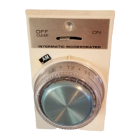
Rotate timer dial clockwise only to prevent damage to the mechanism.

Installation Guide

Enclosure Preparation

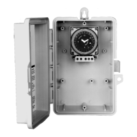
Select knockouts, prepare enclosure for mounting and conduit hubs.

Input Voltage Selection

Set DIP switch to match the applied input voltage (120, 208/240, or 277VAC).

Programming and Operation

Setting the Time

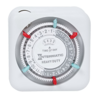
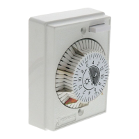
Align day and time markers, then set the minute hand clockwise.

Programming Trippers

Push captive trippers outward for ON periods (15-min increments for 24hr model).

Manual Override Operation

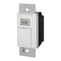
Use switch for permanent OFF ('I') or automatic mode (middle).

Battery Reserve

Built-in battery maintains time for 7 days during power failure.

Terminal Designations and Wiring

Terminal Layout

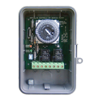
Diagram showing timer, NC, NO, COM, NC2, NO2, COM2 terminals.

Typical Wiring Diagrams

Illustrations for 120VAC, 240VAC, and 277VAC load connections.

Troubleshooting and Support

Troubleshooting Guide

Diagnose common issues like load not turning ON or OFF.

Contact Terminal Transition

Understanding how tripper position affects contact status (IN=OFF, OUT=ON).

Limited One Year Warranty

Details on warranty coverage, limitations, and service.

Overview

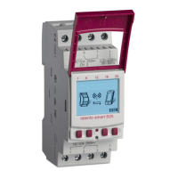
The GM40 Series General Purpose Multi-Voltage Commercial DPDT Time Switch is a versatile electromechanical time control designed for a wide range of applications, including lighting, heating, air conditioning, pumps, motors, and general electrical circuits in residential, commercial, industrial, and agricultural facilities. It offers multi-voltage selection, SPDT and DPDT contacts, and a 40 Amp rating, all housed within a UL TYPE 3R outdoor enclosure.

Function Description:

The GM40 Series time switch is designed to control electrical loads based on a programmed schedule, offering both 24-hour and 7-day models. Users can set specific ON/OFF times using captive trippers on the program dial. The device features an authentic clock face with hour and minute hands for time indication and LED indicators (orange for power, green for status) to provide visual feedback on its operation. A manual override switch allows for temporary deviation from the programmed schedule, enabling the load to be permanently OFF, permanently ON (not explicitly stated for ON, but implied by the OFF/AUTO/ON options), or to operate in automatic mode. For quartz models, a built-in nickel-metal hydride battery provides a 7-day power reserve, maintaining the time of day during power outages. During power outages, relays are de-energized.

Important Technical Specifications:

  • Voltage Options: 120VAC, 208/240VAC, and 277VAC, field-configurable via a DIP switch on the printed circuit board.
  • Contact Configuration: SPDT and DPDT contacts.
  • Contact Ratings (N.O. Contacts):
    • 40A Resistive @ 120~277VAC
    • 1HP, 16FLA, 90LRA @ 120VAC
    • 2HP, 12FLA, 52LRA @ 208~277VAC
    • 30A Ballast @ 120VAC
    • 20A Ballast @ 277VAC
    • 15A Tungsten @ 120VAC
    • 300VA Pilot Duty 120~240VAC
  • Contact Ratings (N.C. Contacts):
    • 30A Resistive @ 120~277VAC
    • 1HP, 12FLA, 30LRA @ 120VAC
    • 2HP, 10FLA, 30LRA @ 240VAC
    • 2A Tungsten @ 120VAC
    • 10A Ballast @ 277VAC
  • Wire Compatibility: Screw box lug terminals, up to one #8 AWG wire. For 40 amp loads, use #8 AWG wire, rated 90°C min.
  • Operating Temperature Range: -40°F to 131°F (-40°C to 55°C).
  • Operating Humidity: 0 - 95% RH non-condensing.
  • Enclosure Dimensions: 8.795" (H) x 6.631" (W) x 2.935" (D).
  • Shipping Weight: 3 lbs.
  • Agency Approvals: UL Listed.
  • Drive Type: Quartz or synchronous drive. Quartz models include a 7-day reserve carry-over.
  • Programming Increments: 15-minute increments for 24-hour models, 2-hour increments for 7-day models.

Usage Features:

  • Multi-Voltage Selection: Easily adjustable DIP switch allows configuration for 120VAC, 208/240VAC, or 277VAC input voltages. The unit is shipped with DIP switches set for 277VAC input voltage.
  • Easy Installation: The enclosure is designed for mounting with three holes, including a keyhole for initial placement. Knockouts are provided for 1/2" and 3/4" conduit.
  • User-Friendly Programming: The program dial is rotated clockwise to align the day of the week and time of day with the triangle marker. Captive trippers are pushed outward to set the ON periods.
  • Manual Override: A three-position manual switch (OFF/AUTO/ON) allows users to temporarily override the programmed schedule.
  • Visual Status Indicators: Orange LED indicates power, and green LED indicates output status (ON/OFF).
  • Captive Trippers: Trippers are integrated into the dial, preventing them from being lost.
  • Real-Time Clock Face: Provides clear time indication with hour and minute hands.
  • Moisture Resistant Conformal Coated Board: Enhances durability in various environments.
  • UL TYPE 3R Enclosure: Suitable for both indoor and outdoor installations, designed to replace all metal enclosures. For outdoor use, raintight or wet local conduit hubs complying with UL 514B are required.
  • "Mechanism Only" (-M) Models: Available for installation in other enclosures or control panels.

Maintenance Features:

  • Troubleshooting Guide: The manual provides a detailed troubleshooting guide for common issues like the load not turning ON or OFF, including steps to check power, DIP switch settings, voltage, manual override switch position, programming dial, and wiring.
  • Easy Access: The interior protective cover and timer mechanism can be removed by releasing spring clips for installation and servicing.
  • Wiring Diagrams: Clear typical wiring diagrams are provided for 120VAC, 240VAC, and 277VAC applications, controlling one or two loads.
  • Grounding: A ground lug is located at the bottom of the enclosure for terminating all ground wires.

Safety Precautions:

  • WARNING: Risk of Fire or Electric Shock: Always disconnect power at the circuit breaker(s) or disconnect switch(es) before installation or servicing. More than one circuit breaker or disconnect switch may be required.
  • Do not use the manual off position for equipment servicing.
  • Use COPPER conductors ONLY.
  • Wire in accordance with national and local electrical code requirements.
  • CAUTION: Risk of Damage to Timer: Rotate timer dial clockwise only. Do not rotate the dial or minute hand counter-clockwise.
  • Do not apply power to the GM40 prior to setting the correct Input Voltage DIP switch.

Intermatic Grasslin GM40 Series Specifications

General IconGeneral
BrandIntermatic
ModelGrasslin GM40 Series
CategoryTimer
LanguageEnglish

Related product manuals