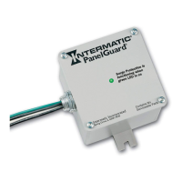
Model IG1200RC3
Type 1 or Type 2 Surge Protective Device
INSTALLATION INSTRUCTIONS
Risk of Electric Shock
WARNING
• Thoroughlyreadinstructionsbeforeinstallingunit.
• InstallationandServicetobeperformedbya
qualiedlicensedelectrician.
• Intendedforindoororoutdooruse.
Type 1 installation:
Atypicalinstallationofatype1SPDwillbeconnectedbetweenthesecondaryoftheservicetransformerandthe
linesideoftheservicepanel.ThisinstallationisintendedtobeinstalledwithoutovercurrentprotectiontotheSPD.
1. Determinelocation:
• Ensureconductorlengthsareasshortandstraightaspossible
forbestperformance.Donotcoilexcesswire.TheSPD
functionsbestifallbendsinwiresarerounded,ideallytoa4”
radius.Hard90degreebendwillreduceefciency.
Cutallleadstothecorrectlength.Donotcoilexcessleads.
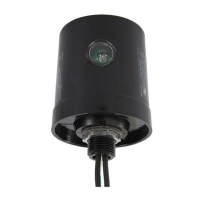
• Installappropriateweatherproofttingsiftheunitistobe
mountedoutside.
2. Ensureallmountingandconnectionsarecorrectandsecure.
OnceenergizedthegreenindicatorLEDwillbeONandvisible
throughthecoveroftheSPD.
Type 2 installation:
Atypicalinstallationofatype2SPDwillbeconnectedtotheloadside
oftheservicepanelandisintendedtobeinstalledwithovercurrent
protectiontotheSPD.
1. Determininglocation:
• Ensureconductorlengthsareasshortandstraightaspossible
forbestperformance.Donotcoilexcesswire.TheSPD
functionsbestifallbendsinwiresarerounded,ideallytoa
4”radius.Hard90degreebendwillreduceefciency.Cutall
leadstothecorrectlength.Donotcoilexcessleads.
• Installappropriateweatherproofttingsiftheunitistobe
mountedoutside.
• IG1240FMP33isalsoavailableforushmountapplications.
2. ConnectthewhitewirefromtheSPDtotheneutralbusbarin
thepanelasshown.
• Connectionmayalsobemadetotheneutral/groundbusbarif
paneldoesnothaveaseparategroundbusbar.
3. Connectthetwoblackwirestoacircuitbreakerasshownin
gure2.ForbestperformancefromSPDthemaximum
recommendedcircuitbreakersizeof240V,20A,2-poleshould
beused.
4. Ensureallmountingandelectricalconnectionsarecorrectand
securelyfastened.OnceenergizedthegreenindicatorLEDwill
beONandvisiblethroughthecoveroftheSPD.
Maintenance:
¡ACVoltageSPD:
• PeriodicallycheckSPDtoensuregreenindicatorLEDisON.
IfgreenLEDisOFFprotectionhasdiminishedandtheSPD
shouldbereplacedimmediately.
• Allwiringmustcomplywithallstateandlocal
electricalcodesincludingtheNationalElectrical
Codeand/orCanadianElectricalCode.
• Suitableforuseonacircuitcapableofdelivering
notmorethan50,000rmssymmetricalamperes.
• Thisunitcontainsnoserviceableparts.
• Thisproductdoesnotprotectagainstdirect
lightningstrikes.
IMPORTANT SAFETY INSTRUCTIONS • SAVE THESE INSTRUCTIONS
MainBreaker
2-Pole,20Acircuit
breakershown
A=Black(Line)
B=Black(Line)
C=Neutral(White)
Type2Installation
120 VAC Two wire single phase with
separate ground.
Found at connections for individual pieces of
equipment such as pumps and single phase motors.
NOTE: Both Black wires connect to Line.
Line
Neutral
Ground
0 v
120 v
120 v
WHITE
BLACK
BLACK
120/240 VAC Three wire with
separate ground.
Found in Main Disconnect Switches, Main
Distribution panels, Load Centers Sub panels
and equipment locations.
Line
Line
Neutral
Ground
120 v
120 v
240 v
120 v
BLACK
WHITE
BLACK
120/240 VAC Three wire with
grounded neutral.
Found at Service entrances and Meter Cans.
Line
Line
Grounded/
Neutral
120 v
120 v
240 v
WHITE
BLACK
BLACK
Type1Installation