EasyManua.ls Logo

Intermatic MIL 72 Series User Manual

Intermatic MIL 72 Series
2 pages
To Next Page IconTo Next Page
Page #1 background imageLoading...
Page #1 background image
MIL 72 Series
24-Hour and 7-Day Universal
Time Switches
APPLICATION
Time based control of lighting, ventilating, heating,
cooling or other electrical loads in commercial and
industrial applications. The MIL 72 time switches are
available with a 24-hour or 7-day program dial with a
single pole/double throw switch.
The MIL 72A series is intended for surface mounting.
The control is completely enclosed in a plastic housing
and includes a terminal cover and sub-base for
installation and hard wiring.
The MIL 72E is intended for flush (panel) mounting. All
units are supplied with a clear plastic cover.
TECHNICAL DATA
Supply Voltage: Synchronous: 24, 120 and 240VAC,
60Hz models
Quartz: 24V AC/DC, 120 and
240VAC 50/60 Hz
Switch Type: SPDT
Switch Rating: 21A @ 250VAC resistive
1350 W tungsten
1HP @ 120VAC
2HP @ 240VAC
16 FLA, 96 LRA, 120VAC ind.
12 FLA, 72 LRA, 240VAC ind.
Power
Consumption: 24V: 0.1VA; 120V: 0.5VA; 240V: 1.0VA
Ambient
Temperature Range: –40°F to 180°F, synchronous units
–14°F to 131°F, quartz units
Reserve Carryover: 150 hours for quartz units
Agency Approvals: UL Recognized
INSTALLATION
To the installer:
1. Read operating instructions carefully.
2. Check the input and output ratings marked on the
unit to make sure this product is suitable for your
supply power and application.
3. Disconnect supply power prior to installation to
prevent electrical shock.
4. Wire in accordance with National and Local
electrical code requirements.
The MIL 72 time switch can be surface, flush or rail
mounted and is also available with an enclosure for
stand-alone applications.
SURFACE MOUNTING—MIL 72A
Remove dust-proof cover, loosen two screws on
op po si te co rners. Remove the housing that
surrounds the time switch and the terminal cover
away from the base.
Place screw through pre-set holes in base and
screw to back of panel or wall.
Wire in accordance with instructions. Depending
upon the specific installation, you may find it more
convenient to have wiring completed before
attaching the base. Replace terminal cover and
push timer firmly onto plug-in base. Now replace
housing and secure with screws.
NOTES:
The MIL 72A may also be DIN rail mounted—
simply break out housing part that fits over rail on
each side.
24V quartz unit will operate on 6VDC, 12VDC, or
24VDC
MIL 72E
(Flush Mounting)
MIL 72A
(Surface Mounting)
Question and Answer IconNeed help?

Do you have a question about the Intermatic MIL 72 Series and is the answer not in the manual?

Intermatic MIL 72 Series Specifications

General IconGeneral
BrandIntermatic
CategoryTimer
Horsepower2 HP
Timing Range24 hours
WeatherproofYes
EnclosureNEMA 3R
Time Interval30 Minutes
TypeMechanical Time Switch
Operating Temperature Range-40°F to 130°F (-40°C to 54°C)

Summary

MIL 72 Series Time Switches

Application

Describes the general use of MIL 72 time switches in commercial and industrial applications for load control.

Technical Data

Lists key specifications including voltage, switch type, ratings, power consumption, and temperature range.

Installation

General guidelines and steps for installing the MIL 72 time switch safely and correctly.

Surface Mounting (MIL 72A)

Detailed procedure for surface mounting the MIL 72A model, including housing removal and attachment.

Panel Mounting (MIL 12E)

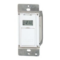
Instructions for flush or panel mounting the MIL 12E model into a square opening.

Wiring

Guidance on connecting wires according to voltage and code requirements for proper operation.

Programming

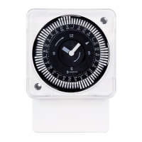
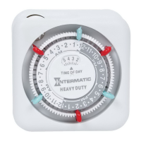
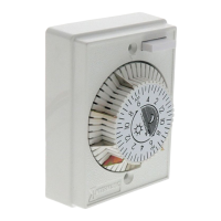
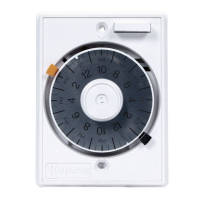
Explanation of how to set the weekly or 24-hour program dial using captive trippers.

Setting Time

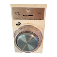
Method for setting the current time on the timer by rotating the minute hand clockwise.

Manual Override

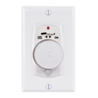
Information about the optional 3-way manual override feature available for MIL 72 units.

Related product manuals