4 Numbers in [brackets] are for 50 Hz international systems. Pub. No. 18-HE122D1-1-EN
Installer’s Guide
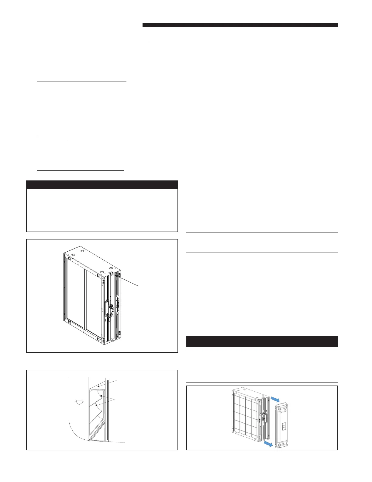
C. DOOR OPERATION
The air cleaner comes with the Power Door installed on
the unit. The Power Door and the internal components
will need to be removed before installation. Follow
these guidelines for removing and reinstalling the door:
REMOVING THE POWER DOOR:
Step 1: Remove the Door Assembly from Whole Home
Air Cleaner by pulling away from the unit assembly.
Place on the at and clean working surface with interior
components facing up. See Figure 10.
Figure 9 Turning Vanes
4. Install the air cleaner such that the airow direc-
tion arrow on the cabinet always points towards the
furnace/ air handler. See Figure 8.
5. The PRE-FILTER must be on the entering airstream
side of the air cleaner cabinet. The mounting ange
on this side of the cabinet has the single row of
holes for attaching ductwork.
6. On side return furnace applications, the air cleaner
may be installed on either side of the cabinet or both
sides of the furnace if two air cleaners are required
to reduce system static.
Position the PRE-FILTER on the side away from
the furnace. The COLLECTION CELL guide key,
installed in the cabinet will only allow the cells to
be installed in the proper direction. Airow direction
must agree with airow arrows on the cabinet.
7. It is recommended that sheet metal turning vanes
be installed inside an elbow on ductwork attached
to the entering airstream side of the air cleaner. This
improves the air distribution over the COLLECTION
CELLS. See Figure 9.
8. Use transition ttings where return air duct dimen-
sions do not match the air cleaners opening dimen-
sions. Gradual transitions are preferred for greatest
eciency. Four inches per linear foot (approximately
20° angle) should be allowed, space permitting.
9. Seal all joints in the return air system to prevent
dust from entering the air stream.
NOTE: Do NOT use a silicon based sealant. This
causes a coating on the FIELD CHARGER pins that
ill decrease the eciency of the air cleaner.
Figure 8 Airow Direction
Airow
Direction
Arrow
Select a location that meets the following:
1. The face of the cell must be at a right angle to the
air stream.
2. Allow a minimum of 28 inches clearance in front
of the air cleaner to permit removal of cells and
Pre-Filter.
3. Flow-through Bypass Humidiers
Excessive bypass air may cause water blow-o,
which will adversely aect system operation and air
cleaner performance. To verify bypass airow, follow
the Bypass Humidier Pre-Installation Checkout and
Set-Up Procedures available through your local dis-
tributor. Ask for publication number 18-CH37D1-*.
Steam and Flow-through Fan Power Duct-mounted
Humidiers
Follow the Humidier installation instructions. These
should only be installed on the supply air side of the
system.
Other Duct Mounted Humidiers
Not recommended for installation with the air cleaner.
Hazardous Voltage!
Disconnect all electric power, including remote
disconnects before servicing. Follow proper lockout/
tagout procedures to ensure the power can not be
inadvertently energized. Failure to disconnect power
before servicing could result in death or serious injury.
Airflow
Tu rning
Vanes
Air Cleaner
Cabinet
Handle the door only by using the handles on the front of
the door. Grasp the door by the handles as depicted in
Figure 10 to remove and replace the door. Do not handle
the door on the edges. Metal edges may be sharp and
could result in injury if the door is not handled properly.
Figure 10 Removing Door Assembly