8 Numbers in [brackets] are for 50 Hz international systems. Pub. No. 18-HE122D1-1-EN
Installer’s Guide
E. ELECTRICAL CONNECTIONS
The air cleaner requires 24 VAC power and indoor fan
signal to operate. A transformer adequately sized to
power both the system and air cleaner is provided with
the air cleaner. Remove the transformer in the indoor
unit and replace with the transformer provided.
NOTE:
- A 50 VA transformer is required for Trane/
American Standard Heating & Air Conditioning
furnace applications.
- For Trane/American Standard Heating & Air
Conditioning air handler applications, a 75 VA
transformer is required. Replacement of the fuse
is also needed. Remove the quick blow 5 Amp fuse
and connect the supplied 3.2 Amp slow blow fuse
assembly in its place.
NOTE: WHEN MORE THAN ONE WHOLE HOUSE
AIR CLEANER is used, the 24 volt transformer
which supplies power to the air cleaner will need to
be increased by 25 VA for each additional air cleaner
added.
NOTE: Trane/American Standard Heating & Air
Conditioning dual circuited air handlers matched
with heat pumps and Trane/American Standard
Heating & Air Conditioning oil furnaces will require
an accessory Transformer KIT# BAYTRANS12024◆
to power the air cleaner. Do NOT replace air handler
transformer with the transformer supplied with the
air cleaner.
NOTE: Provide adequate strain relief for the low
voltage cable at the indoor unit.
DO NOT attach the power/control cable to a 120 Volt
EAC tap. The air cleaner uses 24 Volt power. Fail-
ure to use 24 VAC results in permanent damage to
the air cleaner.
• Plug the air cleaner power/control cable into the air
cleaner door and route the cable into the indoor unit
low voltage wiring location.
• Connect the power/control wiring per Figures 20 &
20A.
NOTE: Wiring penetration must be sealed.
NOTE: For non-Trane/American Standard Heating
& Air Conditioning systems order a 120 VAC to 24
VAC transformer, KIT# BAYTRANS12024◆ to provide
24 volt power only to the air cleaner. Access to 120
VAC outlet is required.
• Connect the power/control wiring per Figures 20 &
20A.
NOTE: Trane/American Standard Heating & Air
Conditioning Communicating Furnaces require KIT
# BAYACCECOMM101.
NOTE: Wiring diagrams for the Communicating Air
Handler, Communicating Furnaces and Oil Furnaces
are on pages 9-10, 11-13 and 14 respectively.
D
BLUE
GREEN
BROWN
BLACK
RED
WHITE
BLUE
GREEN
BROWN
BLACK
RED
WHITE
BLUE
BROWN
BROWN
Data Line
BLACK
GRD
RED
Unused
Unused
GREEN
WHITE
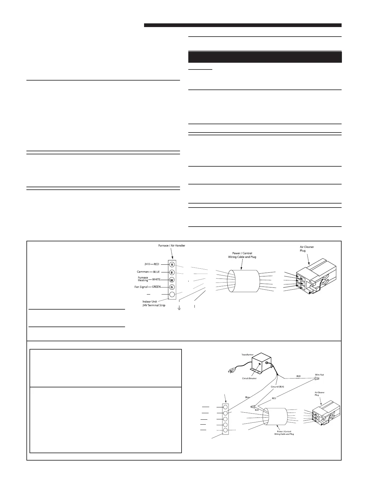
Air Handler may not have a Low Voltage Terminal board. Connect Electronic Air Cleaner wires to
the Air Handler Low Voltage Color coded wires.
Install Transformer, one is supplied with the Electronic Air Cleaner, in the Furnace or Air Handler.
BLUE
Unused
GREEN
Furnace / Air Handler
BROWN /
Dataline
Indoor Unit
24 V Te rminal Strip
Unused
WHITE
RED
BLUE
GREEN
WHITE
24 V
Common
Fan Signal
Furnace
Heating Signal
R
B
W
G
D
BROWN
Data Line
BLUE
GREEN
BROWN
BLACK
RED
WHITE
The ◆ represents an alpha character.
Figure 20 - Wiring Diagram
Communicating Mode
NOTE: The Black wire must be con-
nected to chassis ground to ensure
proper operation.
BAYTRANS12024◆ Transformer
• Transformer must have a grounded 120 VAC
power source. Do not defeat ground plug on
the transformer.
• Mount transformer to building structure with
the four provided wood screws.
Transformer not applicable to 50 Hz units.
NOTE: BAYTRANS12024C complies with the Cali-
fornia Code of Regulation,Title 20, Sections 1601
through 1608 dated December 2006. BAYTRAN-
S12024A with vendor’s manufacturing date codes
after 0625 (YYWW) cannot be installed in California
because the transformer does not satisfy the
requirements set forth by California Code of Regula-
tions, Title 20, Sections 1601 through 1608 dated
December 2006.