6 Numbers in [brackets] are for 50 Hz international systems. Pub. No. 18-HE122D1-1-EN
Installer’s Guide
DOWNFLOW FURNACE INSTALLATION
NOTE: On 90% Downow Furnaces, the intake and
exhaust (ue) are located on top. A eld supplied
transition is needed between the furnace and the
air cleaner. The transition must be long enough
to avoid any interference between the intake and
exhaust pipe routing and the door of the air cleaner.
The door and internal components must be remov-
able for servicing.
NOTE: Optional Side Vent Kit BAYVENT500A may
be used if a 90% downow furnace is installed
with a whole house air cleaner. This optional side
venting kit allows access to the front door of the
whole house air cleaner for easy lter cleaning and
maintenance. This kit eliminates the need for the
transition between the furnace and air cleaner.
1. See door operation Section C. Remove the PRE-
FILTER, FIELD CHARGER, and both COLLECTION
CELLS. Set the components aside until the cabinet
is installed and the indoor unit is in place.
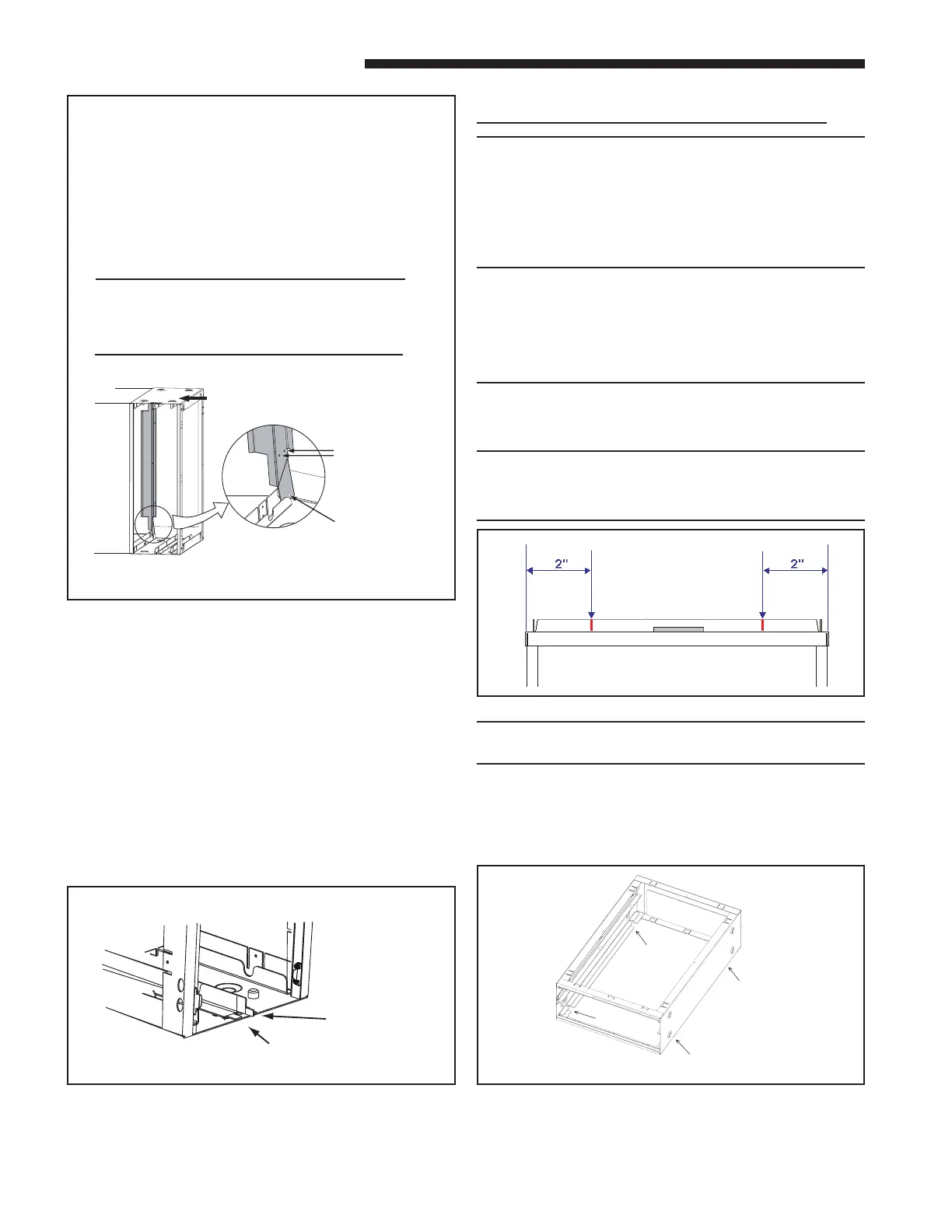
NOTE: Cut the front duct ange 2" from each side
and fold at to clear the Power Door latches. Some
applications may require a transition for piping
clearances. See Figure 17.
NOTE: Remove lter rack from downow Furnace
and discard.
2. Bend the 4 mounting tabs down on the two sides of
the air cleaner cabinet. These can be used to attach
the air cleaner cabinet to the furnace. See Figure
18.
3. Install the self-adhesive gasket material on the side
of the air cleaner cabinet ange that will mate with
the indoor unit. This ange has a double set of
holes. See Figure 14.
UPFLOW AIR HANDLER APPLICATIONS ONLY
9.
Position the bae onto the air cleaner as indi-
cated in Figure 15. The bae should be posi-
tioned on the leaving air side of the air cleaner
cabinet opposite the power door. Ensure that
the bracket is located correctly inside the air
cleaner enclosure so that the bae or screws
do not interfere with the lter cell installation.
(See Figure 15 inset.)
NOTE: The upow air handler bae is re-
quired to protect the air cleaner in the event of
a drain pan overow. This bae is required
for all upow air handler installations.
10. Install unit in place and secure.
11. Reinstall the FIELD CHARGER and lock into place
by bending one locking tab on the cabinet. See
Figure 16.
12. Reinstall the PRE-FILTER and COLLECTION
CELLS.
13.
Each cell must be oriented with handles toward the
front.
14. The door can be installed in either direction. See
Door Operation Section C.
15. Remove stickers (two stickers both are 5.5" x 7.5")
from packet and attach to furnace, air handler, or
ductwork in a location visible to the homeowner.
16. Demonstrate Maintenance (Section H) and Door
Operation (Section C) to the homeowner.
Figure 18 Mounting Tabs
Figure 17 Duct Flanges
Figure 16 Locking Tab
Attach upflow air
handler baffle to air
cleaner and air
handler using the
self-tapping sheet
metal screws
provided.
Be sure tab at end
of baffle is INSIDE
the channel before
attaching.
AIRFLOW
Figure 15 Upow Air Handler Bae Installation Details
Field Charger Locking Ta b
Actuator Tab for
Interlock Switch