NOTE: DIAGRAMS & ILLUSTRATIONS NOT TO SCALE.
7
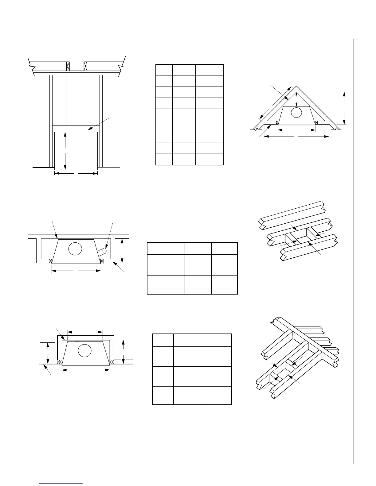
FRAMING SPECIFICATIONS
Figure 10
Figure 11
Figure 12
Figure 14
Figure 15
Figure 13
Framing Dimensions
A 41 ¹⁄₄" 1048 mm
B 37 ¹⁄₂" 953 mm
C 28 ³⁄₄" 730 mm
D 15 ³⁄₈" 391 mm
E 70" 1778 mm
F 35" 889 mm
G 20 ⁵⁄₈" 524 mm
H 19 ⁵⁄₈" 498 mm
J 49 ¹⁄₂" 1257 mm
Framing Dimensions for Roof
Pitch C D*
0/12 14 ¹⁄₂" 14 ¹⁄₂"
(368 mm) (368 mm)
6/12 14 ¹⁄₂" 17"
(368 mm) (442 mm)
12/12 14 ¹⁄₂" 21 ¹⁄₂"
(368 mm) (546 mm)
Framing Dimensions for Ceiling
Flue Type A B
FTF8 Vertical 14 ¹⁄₂" 14 ¹⁄₂"
(368 mm) (368 mm)
FTF8 Offset 30° 14 ¹⁄₂" 25"
(368 mm) (635 mm)
Note: All framing dimensions calcu-
lated for 1/2" dry wall at the fireplace
face. If sheathing the chase or finish-
ing with other thickness materials,
calculations will need to be made.
* Perpendicular to roof ridge
A
B
Ceiling Framing
C
D
Roof Framing
Header
Fireplace Framing
B
A
A
G
Inside Chase
Back Wall of Chase/Enclosure
Including Finising Materials if any
Rough
Framing Face
(Unfinished Shown)
FOAK Combustion
Air Kit
A
Outside Chase
G
C
H
Back Wall of Chase/Enclosure
Including Finising Materials
if any
Rough
Framing Face
(Unfinished Shown)
Corner Installation
J
D
A
E
F
Back Wall of
Chase/Enclosure
Including Finising
Materials
if any
Rough
Framing Face
(Unfinished Shown)