6
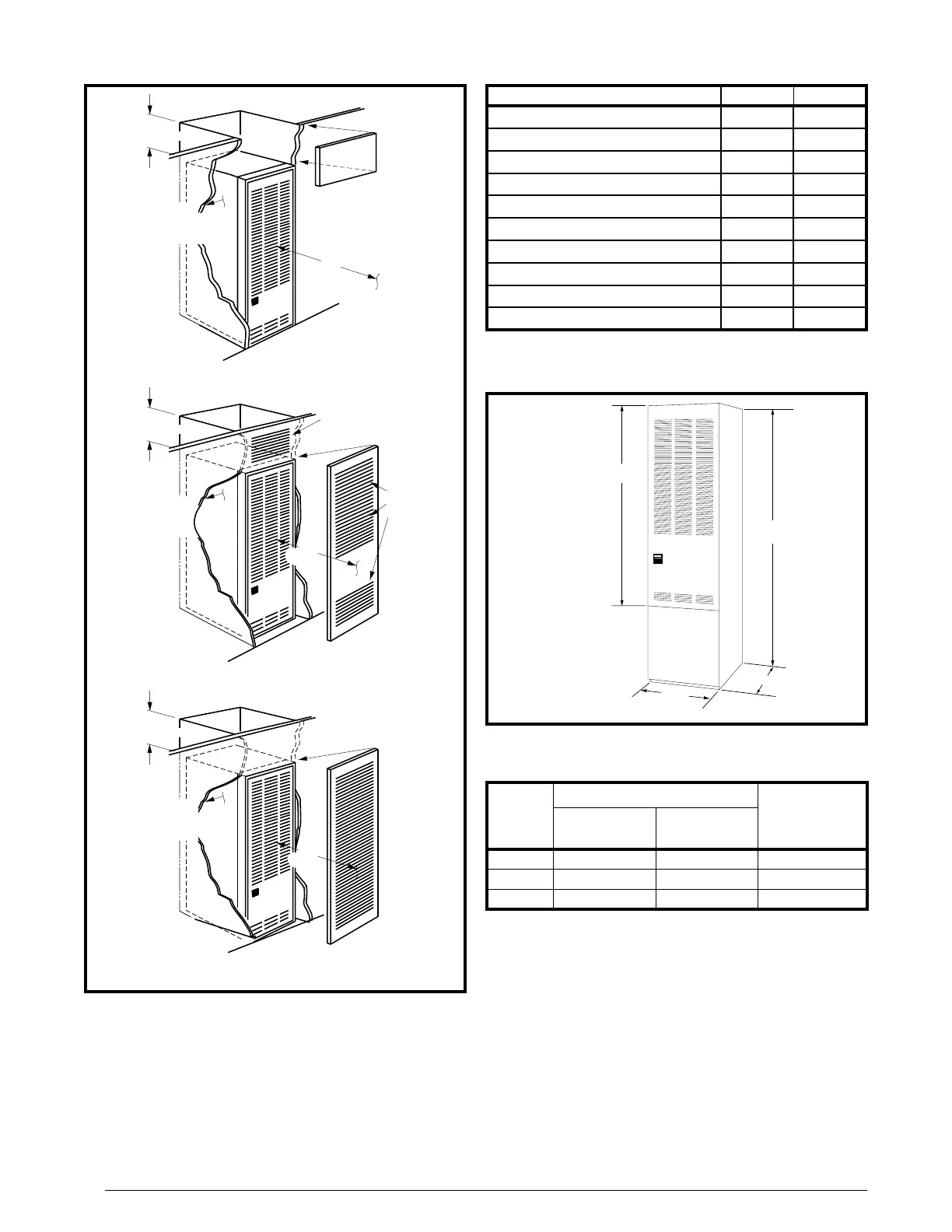
Figure 1 Figure 2 Figure 3
Figure 3.
Removable access
panel should be
installed above
furnace door frame
to access roof jack
Nearest
Wall or
Partition
18"
(457 mm)
6" (152 mm)
Top Clearance
0" Side
Clearance
to Furnace
Cabinet
6" (152 mm)
Top Clearance
0" Side
Clearance
to Furnace
Cabinet
Provide min. 235
sq. in. (1516 cm )
open free area in
front or side wall
2
or
In closet
door
located
at top,
center
or bottom
CLOSET DOOR
6" (152 mm)
Top Clearance
Provide min. 250
sq. in. (1613 cm )
open free area in
front or side wall
2
a fully
louvered
door may
be used
CLOSET DOOR
6"
(152 mm)
1"
(25 mm)
0" Side
Clearance
to Furnace
Cabinet
or
in closet
door
Figure 2. Closet Installation
Figure 1.
Figure 4
“A”- 56"
23 3/4"
“B”- 76"
“A” Model
w/o Coil
Cabinet
“B” Model
w/Coil
Cabinet
19 3/4”
Figure 4.
Table 1
Table 1. Minimum Clearances
Front 6” 18”
Back 0” 0”
Sides 0” 0”
Roof Jack 0” 0”
To p 6” 6”
Top and Sides of Duct 0” 0”
Bottom of Duct — —
B Cabinet 0” 0”
A Cabinet (w/ coil box) 0” 0”
A Cabinet (w/o coil box) 1/4” 1/4”
Table 2
Table 2. Blower Assemblies
NO.
(TONS)
903773 10 x 8 1/4 2, 2½ & 3
903413 11 x 8 1/2 2, 2½, 3 & 4
903890 11 x 8 3/4 2, 2½, 3, 4 & 5
 Loading...