9
Alternate Attachment Method
The standard duct connector is designed for use on ducts
12” in width. However if there is insufficient clearance to
bend the duct connector tabs, this alternate attachment
method may be used.
1. Score and cut the top of the supply air duct as indicated
in Option 1 or Option 2. See Figure 11 (page 10).
If Option 1 is selected, cut out the metal from
the shaded area.
2.Foldthetwoaps(Options1or2)uptoformtheopening
for the duct connector.
3. Install the duct connector with the bottom tabs extending
into the supply air duct.
4. Bend the tabs on the bottom of the duct connector
upwards and as tight as possible against the supply
air duct. See Figure 12 (page 10).
5.Form the aps (Options 1 or 2) up against the duct
connector as tight as possible.
6.Securetheductconnectorapstothesupplyairduct
with staples (3 minimum) or if a 2x block/joist is not
provided, use sheet metal screws (2 minimum).
The duct connector tabs may be attached to
the air duct with sheet metal screws or other suitable
fasteners as long as the duct connector and the air duct
are securely attached.
7. Seal all connections with industrial grade sealing tape
or liquid sealant.
Requirements for sealing ductwork vary
from region to region. Consult with local codes for
requirements specific to your area.
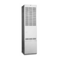
Figure 6
FLOOR CUT-OUT
FOR STANDARD
DUCT CONNECTORS
C
L
C
L
C
L
24"
23 1/4"
21 3/4"
14 1/2"
2 1/4"
2 3/4"
20"
CUT-OUT FOR
OPTIONAL
COOLING COIL
REAR WALL OF CLOSET OR ALCOVE
1 3/4"
2"
3/4"
C
L
C
L
C
L
10"
C
L
FURNACE OUTLINE
14 1/2"
ALT FUEL-LINE
ENTRY 1 1/4" Dia.
FURNACE
OUTER
DOOR
FUEL
LINE
1 3/4"
3/4"
1 7/8"
2 7/8"
Figure 6.
Standard Duct Connectors
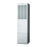
Figure 7
FLOOR
CUT-OUT FOR
ROUND DUCT
(14 1/4” DIAMETER)
C
L
C
L
C
L
C
L
24"
23 1/4"
21 3/4"
20"
CUT-OUT FOR
OPTIONAL
COOLING COIL
ALT FUEL-LINE
ENTRY 1 1/4" Dia.
FURNACE
OUTER
DOOR
REAR WALL OF CLOSET OR ALCOVE
FUEL
LINE
1 3/4"
2"
3/4"
C
L
C
L
10"
FURNACE OUTLINE
1 3/4"
10"
3/4"
1 7/8"
2 7/8"
C
L
Figure 7.
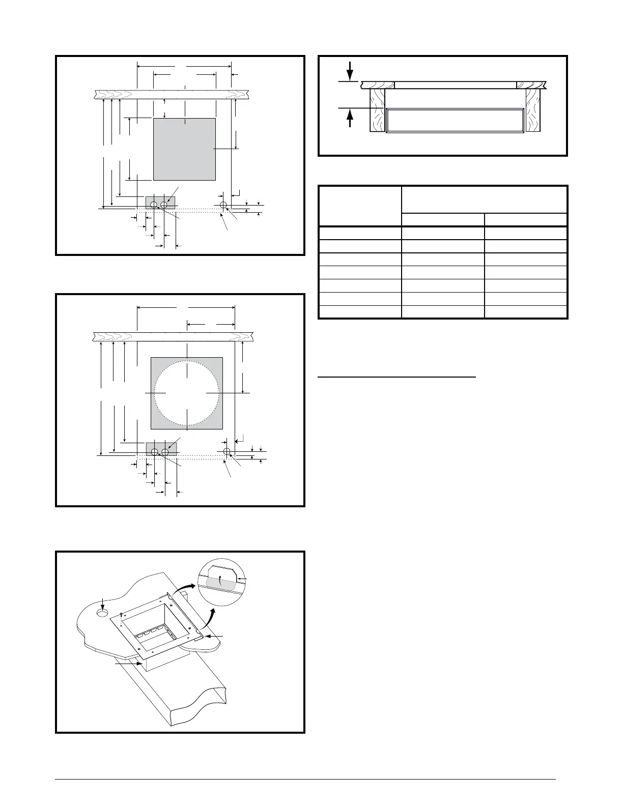
Figure 8
Bend tabs
up 90°
Mounting Plate
Duct
Connector
Connector
Tabs
Supply
Air Duct
Hole for
Gas Line
Wood Floor
Figure 8. Standard Duct Connector Installed
Figure 9
“X”
FLOOR OPENING
FLOOR
CAVITY
SUPPLY AIR DUCT
Figure 9.
Table 3
7/8” / (22) 901987A 904008
2” / (51) 901988A 904009
4-1/4” / (108) 901989A 904010
6-1/4” / (159) 901990A 904011
8-1/4” / (210) 901991A 904012
10-1/4” / (260) 901992A 904013
12-1/4” / (311) 901993A 904014
Dimensions shown as Inches / (Millimeter)
Table 3.
 Loading...