87IO
SAVE THESE INSTRUCTIONS
Page 9
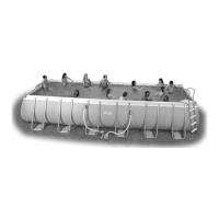
(87IO) ROUND METAL FRAME POOL ENGLISH 7.5” X 10.5” PANTONE 295U 05/28/2007
SSEETT--UUPP IINNSSTTRRUUCCTTIIOONNSS
POOL SET UP (continued)
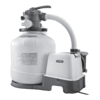
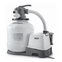
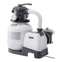
This pool may have been purchased with the Intex Krystal Clear™
filter-pump. The filter-pump has a separate set of installation instructions
and is to be set-up after assembling this unit.
1. • Find a flat, level location that is free and clear of stones, branches or other sharp objects
that may puncture the pool liner or cause injury.
• Open the carton containing the liner, joints, legs, etc., very carefully as this carton can be
used to store the pool during the winter months.
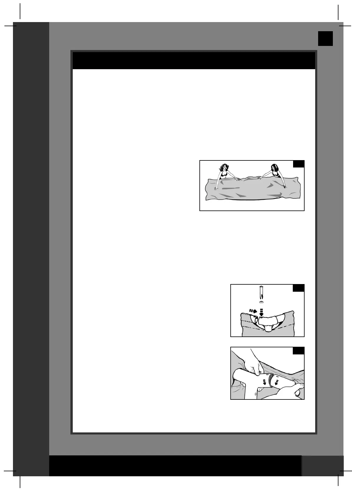
• Remove the ground cloth (10) and spread over the area cleared, and then remove the
liner (7) and spread it out over the ground
cloth with the drain valve towards the
draining area. Place the drain valve away
from the house. Allow the sun to warm up
the liner before inserting the beams (6)
into the sleeve openings.
IMPORTANT: Do not drag the pool liner
across the ground as this may result in
leaks or other damage (see drawing 1).
• During the set-up of this pool liner point the hose connections or openings in the
direction of the electric power source. The outer edge of the assembled pool is to be
within reach of the electrical connection for the optional filter-pump.
2. • The frame pool’s legs (8) and beams (6) fall into two groups. The larger diameters are
the horizontal beams that are slid (pushed) into the sleeve openings at the top of the
liner. The smaller diameters are the vertical legs. Both these legs and beams fit into the
T-joints (3).
• Starting at any location, but always working in the same
direction, push the horizontal beam into the sleeve.
Once the beam is centered take one of the T- joints and
using the connection pin (1), attach the joint to one end
of the beam by inserting the pin through the seal (2)
and in the pre-drilled holes. Repeat this procedure in a
circular fashion until all the beams and joints have been
connected (see drawing 2.1).
The last joint connection may be difficult to
complete, but can be easily done by simultaneously
raising this last joint and beam about 2 inches (5 cm),
and inserting the beam into the joint while lowering
these pieces to their normal position. The beam will
slide into the joint (see drawing 2.2). Make sure the
last joint is fully assembled before proceeding to
assembling the legs.
7
1
1
2
6
3
2.1
2.2
3
 Loading...