SECTION 4—ASSEMBLY
Portable Patient Lift and Sling 16 Part No 1024492
SECTION 4—ASSEMBLY
Assembly of the Patient Lift
WARNING
Use only Invacare parts in the assembly of this lift. The base legs, the mast, boom,
pump assembly and the swivel bar are manufactured to specifications that assure
correct alignment of all parts for safe functional operation.
CAUTION
DO NOT run the lift until it is fully assembled.
Follow the assembly instrudctions in the Owner’s Manual for proper assembly of
this lift. Failure to do so could result in damage to the push handle of the lift, render-
ing it inoperative.
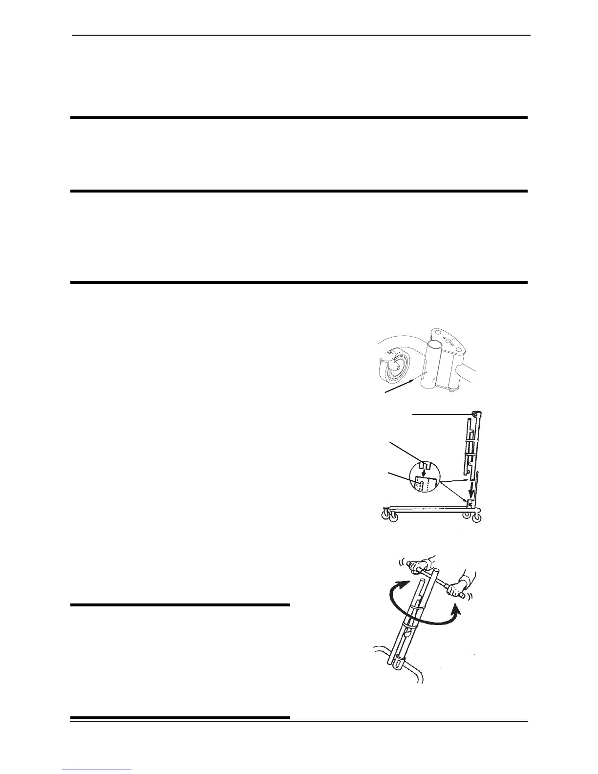
NOTE: For this procedure, refer to FIGURE 4.1 and FIGURE 4.2.
Base, Mast and Boom Assembly
1. Unpack the components from the
shipping cartons.
2. Remove the locking screw from the
bottom of the base.
NOTE: The bottom of the mast assembly will
have a notch.
3. Match the notch at the bottom of the
mast assembly with the tabs inside the
socket of the base assembly.
4. Insert the mast assembly into the socket
and onto the tabs.
5. Turn the mast assembly to make sure
that the notch is locked on the tabs of
the socket.
NOTE: If the mast does not turn, the mast is
centered and locked in place.
6. Insert the locking screw into the bottom
of the base and securely tighten.
WARNING
The mast may be removed from the
base for storage or transporting. Each
time the mast is removed and returned
to the socket of the base, the mast
MUST be locked into the socket of the
base assembly.
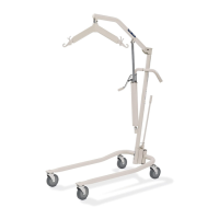
FIGURE 4.1 Assembly of the Patient Lift -
Base, Mast and Boom Assembly
Locking Screw
Bolt and Locknut
Bottom of mast notch
Top Inside of the
Socket of the
Base Assembly