Do you have a question about the Inverex Axpert King 3.2KW and is the answer not in the manual?
Describes assembly, installation, operation, and troubleshooting of the unit.
Provides safety and installation guidelines, and information on tools and wiring.
Lists key features of the multi-function MPPT solar inverter.
Illustrates the basic application and components of the solar inverter system.
Details the items to check upon receiving the unit for damage.
Instructions for preparing the unit, including removing the bottom cover.
Guidance on selecting a suitable location and mounting the inverter securely.
Provides instructions and specifications for connecting the battery to the inverter.
Step-by-step guide for connecting AC power input and output terminals.
Instructions for connecting the PV modules to the inverter's PV input.
Parameters to consider when selecting PV modules for the system.
Steps to complete the physical installation by replacing the bottom cover.
How to connect the inverter to a PC for monitoring software installation.
Procedure for turning the inverter unit on and off using the switch.
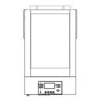
Overview of the inverter's front panel controls, indicators, and LCD display.
Explanation of the various icons displayed on the inverter's LCD screen.
Details on how load percentage and VA/Watt are displayed.
Icons indicating different operating modes like mains, PV, bypass.
Information about disabling unit alarms and BLE status.
Overview of configurable setting programs and their descriptions.
Configuring the battery type for optimal charging and management.
Setting for automatic restart after an overload condition.
Setting for automatic restart after an over-temperature event.
Setting the inverter's output frequency (50Hz, 60Hz, or Auto).
Configuring the inverter's operational priority based on AC and PV sources.
Setting the maximum current drawn from the utility for charging batteries.
Configures voltage threshold to switch back to utility in SBU priority.
Configures voltage threshold to switch to battery mode in SBU priority.
Configures the priority for charging from solar or AC sources.
Enables or disables audible alarms for various events.
Sets whether the display returns to default or stays on the current screen.
Controls the ON/OFF state of the LCD backlight.
Configures audible alerts when the primary power source is interrupted.
Enables or disables the bypass function under specific conditions.
Enables or disables the recording of fault codes for troubleshooting.
Sets the voltage threshold for shutting down DC output to protect batteries.
Sets the duration for the bulk charging stage.
Enables or disables the battery equalization function for maintenance.
Sets the target voltage for the battery equalization stage.
Sets the duration for the battery equalization stage.
Sets the timeout for the battery equalization stage.
Sets the frequency for performing battery equalization cycles.
Allows immediate activation of battery equalization, overriding scheduled times.
Resets the recorded PV and load energy data.
Sets the minute component of the system's real-time clock.
Sets the hour component of the system's real-time clock.
Sets the day component of the system's real-time clock.
Sets the month component of the system's real-time clock.
Sets the year component of the system's real-time clock.
Shows the default display screen for input and output voltage.
Displays the current input frequency of the unit.
Shows the voltage being generated by the PV panels.
Displays the current being generated by the PV panels.
Shows the power being generated by the PV panels.
Indicates the current flow for AC, PV, or combined charging.
Shows the power flow for AC, PV, or combined charging.
Displays both the battery voltage and the output voltage simultaneously.
Displays the current output frequency of the inverter.
Indicates the load percentage relative to the inverter's capacity.
Displays the current load on the inverter in Volt-Ampere (VA).
Displays the current load on the inverter in Watts (W).
Shows the battery voltage and the DC discharging current.
Displays daily energy generation from PV and load consumption.
Shows monthly energy generation from PV and load consumption.
Shows yearly energy generation from PV and load consumption.
Displays total energy generation from PV and load consumption.
Displays the current system date.
Displays the current system time.
Shows the version information for the main CPU.
Shows the version information for the secondary CPU.
Shows the version information for the Secondary BLE module.
Shows the version information for the SCC.
Describes the inverter's standby operational state, including battery charging.
Explains the inverter's behavior and bypass capability during fault conditions.
Describes operation in Bypass and ECO modes, including power sources.
Describes operation when connected to the utility line and charging the battery.
Describes operation when the inverter provides output power from battery and PV.
Fan is locked when inverter is off.
Over temperature condition detected within the inverter.
Battery voltage is too high.
Battery voltage is too low.
Output short circuited or internal over temperature.
Output voltage is too high.
Overload condition has timed out.
Bus voltage is too high.
Bus soft start sequence failed.
Power Factor Correction (PFC) over current or surge.
Over power (OP) over current or surge.
Bus voltage is too low.
Inverter soft start sequence failed.
Over DC voltage detected in AC output.
Current sensor has failed.
Output voltage is too low.
PV voltage is exceeding its limitation.
Fan is locked when the inverter is operating.
Over temperature condition detected.
Battery is over-charged.
Low battery voltage detected.
Overload condition detected.
Output power is being derated.
PV energy generation is low.
High AC input during BUS soft start.
Communication between components has been interrupted.
Battery equalization process is active.
Battery is not connected to the unit.
Steps to enable and apply the battery equalization function via settings.
Explains the conditions and stages for battery equalization to occur.
Details on the duration and timeouts for the equalization charging stage.
Technical specifications for the inverter operating in Line Mode.
Technical specifications for the inverter operating in Battery Mode.
Technical specifications related to utility and solar charging modes.
Technical specifications for the inverter in ECO and Bypass modes.
General technical specifications, including safety, environment, and dimensions.
Troubleshooting steps for automatic shutdown during the startup phase.
Troubleshooting steps for when the unit fails to power on or respond.
Diagnosing why the unit operates in battery mode when mains power is available.
Troubleshooting repeated switching of the internal relay during startup.
Addressing continuous buzzer sounds and a solid red LED indicator.
| Input Voltage | 230 VAC |
|---|---|
| Output Voltage | 230 VAC |
| Battery Voltage | 24 VDC |
| Max PV Array Power | 4000W |
| Max PV Array Open Circuit Voltage | 145VDC |
| Efficiency | 93% |
| Frequency Range | 50 Hz/60 Hz (Auto sensing) |
| Output Voltage Regulation | 230VAC ± 5% |
| Transfer Time | 10 ms (For Personal Computers); 20 ms (For Home Appliances) |
| Waveform | Pure sine wave |
| Maximum Charging Current | 80A |
| Maximum Efficiency | 93% |
| Max Solar Charge Current | 80A |
| Max AC Charge Current | 60A |
| Rated Power | 3200W |
| Selectable Voltage Range | 170-280 VAC (For Personal Computers); 90-280 VAC (For Home Appliances) |
| Surge Power | 6400W |
| Protection | Overload, Over temperature, Short circuit |
| Communication | USB/RS232 |
| Operating Temperature | 0°C to 55°C |