M
martinezjacobSep 8, 2025
What to do if my Inverex NITROX-15KW displays AC Line V,W low voltage?
- JJasmine MaldonadoSep 8, 2025
If your Inverex Inverter displays AC Line V,W low voltage, inspect the AC supply for issues causing low voltage.
What to do if my Inverex NITROX-15KW displays AC Line V,W low voltage?
If your Inverex Inverter displays AC Line V,W low voltage, inspect the AC supply for issues causing low voltage.
What should I do if my Inverex NITROX-15KW displays a DC over current error?
If your Inverex Inverter is showing a DC over current error, you should check the DC input connections and reduce the current to resolve the issue.
What to do if the DC busbar voltage is too high in my Inverex Inverter?
If the DC busbar voltage is too high in your Inverex Inverter, reduce the input voltage to the DC busbar.
What to do if the DC busbar voltage is too low in my Inverex Inverter?
If the DC busbar voltage is too low in your Inverex Inverter, increase the input voltage to the DC busbar.
What to do if my Inverex NITROX-15KW shows AC grid U over current?
If your Inverex Inverter displays an AC grid U over current, you should check the U phase for overload conditions.
What to do if my Inverex NITROX-15KW displays 'Reactor C phase over current'?
If your Inverex Inverter displays 'Reactor C phase over current', inspect the reactor C connections and reduce the current.
What to do if my Inverex Inverter displays 'Reactor A phase over current'?
If your Inverex Inverter displays 'Reactor A phase over current', inspect the reactor A connections and reduce the current.
What to do if my Inverex Inverter displays 'Reactor B phase over current'?
If your Inverex Inverter displays 'Reactor B phase over current', inspect the reactor B connections and reduce the current.
What to do if my Inverex Inverter displays AC Line W,U low voltage?
If your Inverex Inverter displays AC Line W,U low voltage, inspect the AC supply for issues causing low voltage.
What to do if my Inverex NITROX-15KW Inverter displays AC Line V,W over voltage?
If your Inverex Inverter is showing an AC Line V,W over voltage error, check and adjust the AC voltage levels.
Explains the meaning of various safety symbols used throughout the manual.
Provides essential safety rules for operating and maintaining the inverter.
Details the process for safely connecting DC power input terminals.
Explains how to connect the AC power output terminals correctly.
Provides the procedure for safely starting the inverter.
Provides the procedure for safely shutting down the inverter.
Lists all possible error codes and their corresponding descriptions.
Offers solutions and steps to resolve common inverter errors.
Presents detailed technical data and specifications of the inverter models.
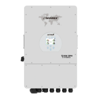
The Inverex NITROX series of PV Solar On-Grid Inverters are three-phase string power inverters designed to convert DC power from solar panels into AC power, which can then be fed directly into the electrical grid. These inverters are suitable for various applications, from residential to commercial, and are available in models ranging from 12KW to 25KW, specifically NITROX-12KW-3Ph-5G, NITROX-15KW-3Ph-5G, NITROX-20KW-3Ph-5G, and NITROX-25KW-3Ph-5G.
The primary function of the NITROX inverter is to facilitate the integration of solar photovoltaic systems with the existing electrical grid. It takes the variable DC output from solar PV strings and converts it into stable AC power that matches the grid's voltage and frequency requirements. This allows for the efficient utilization of solar energy, either for self-consumption within a property or for feeding surplus energy back into the grid.
The inverter incorporates a sophisticated control system that ensures optimal power harvesting from the solar panels through Maximum Power Point Tracking (MPPT). This technology continuously adjusts the operating point of the PV array to maximize power output under varying sunlight and temperature conditions.
An optional but significant feature is the external limiter function. This allows the inverter to monitor and control its output power to prevent excess power from being fed back into the grid. This is particularly useful in regions or installations where zero-export is mandated or desired. The limiter collects voltage and current data from the AC lines and sends control signals to the inverter to balance the power between the inverter's output and the local load, ensuring that any surplus power is consumed locally rather than exported. The limiter offers two anti-backflow modes: minimum mode, which controls power based on the phase with the lowest power to prevent reverse current in any phase, and average mode, which controls output based on the average total power of the three-phase load. The minimum mode is the default to ensure no anti-backflow occurs.
The inverter also includes comprehensive protection features to ensure safe and reliable operation. These include DC reverse-polarity protection, AC short circuit protection, AC output overcurrent and overvoltage protection, insulation resistance protection, ground fault monitoring, surge protection, islanding protection, and temperature protection. An integrated DC switch is also an optional safety feature.
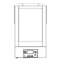
The NITROX inverter is designed for user-friendly operation and monitoring. It features a dot matrix LCD display that provides real-time information about the inverter's operational status, including current power output, total energy generation (daily, monthly, yearly, and historical), and various system parameters. The display also shows warning messages and malfunction indicators, allowing users to quickly identify and address potential issues.
Navigation and parameter adjustment are managed through a set of four buttons on the inverter panel: UP, DOWN, ESC, and ENTER. These buttons allow users to scroll through different display screens, modify adjustable parameters, and access various sub-menus such as "System Param," "Running Param," "Protect Param," and "Comm. Param."
The inverter's status is visually indicated by four LEDs:
For remote monitoring, the inverter is equipped with a wireless remote monitoring function, typically through a Wi-Fi Plug (optional accessory). This plug connects the inverter to a network, enabling users to monitor system performance via a web server or a dedicated mobile application. The installation and configuration of the Wi-Fi Plug are detailed in separate instructions, ensuring seamless integration into a smart home or facility management system.
Installation is designed to be straightforward, with the inverter intended for wall-mounted installation. Clear guidelines are provided for selecting an appropriate installation location, emphasizing good ventilation, protection from direct sunlight, rain, and snow, and maintaining adequate clearance around the unit for heat dissipation. The installation process involves securing a wall mounting bracket and then hanging the inverter onto it, with specific instructions for electrical connections for both DC input from solar panels and AC output to the grid. Fast connectors are used for both DC and AC connections to simplify the process.
Safety is paramount during installation and operation. The manual provides detailed safety warnings and instructions, including precautions against electric shock, burns, and proper handling of high voltage components. It stresses the importance of qualified personnel for installation and maintenance, adherence to local electrical standards, and specific sequences for disconnecting AC and DC power before any maintenance work.
The NITROX string type inverter generally does not require regular, intensive maintenance. However, to ensure optimal performance and longevity, some basic maintenance practices are recommended:
The inverter's design incorporates robust components and undergoes rigorous testing to ensure reliable and permanent operation, minimizing the need for frequent repairs. Its built-in leakage current detection circuit is a key safety feature, and if an external leakage current protection device is used, its operating current must be greater than 300mA to avoid interference with the inverter's proper functioning.
| Model | NITROX-15KW |
|---|---|
| Rated Power | 15KW |
| Output Frequency | 50Hz/60Hz |
| Waveform | Pure Sine Wave |
| Phase | 3 Phase |
| Output Power | 15000W |
| Protection | Overload, Short Circuit, Over Temperature |