2-12
Notes:
z The specified wire length is for a pair of conductors from the solar, load or battery
source to the controller (1-way distance).
z Figures are in meters (m) and feet (ft).
z For 24 volt systems, multiply the 1-way length in the table by 2.
z For 48 volt systems, multiply the 1-way length in the table by 4.
Ground Connection:
Use the grounding terminal in the wiring compartment to connect a copper wire to an earth
ground or similar grounding point. The grounding terminal is identified by the ground
symbol shown below that is stamped into the enclosure:
The minimum size of the copper grounding wire:
• SunStar-30A (SS-30C) 4 mm
2
(12 AWG)
• SunStar-45A (SS-45C) 6 mm
2
(10 AWG)
• SunStar-60A (SS-60C) 10 mm
2
( 8 AWG)
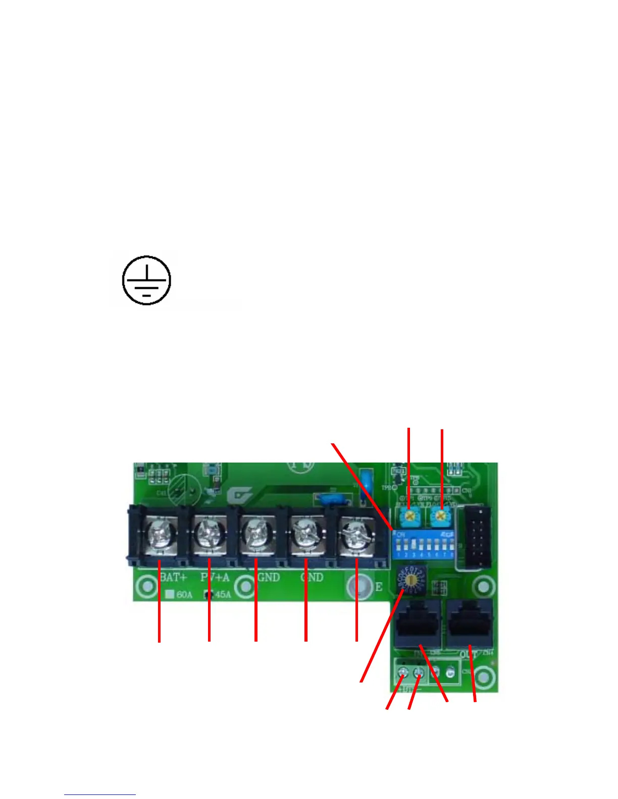
Connect the Power Wires:
First, confirm that the DIP switch #1 is correct for the operating mode intended.
Battery
Positive +
PV+ /
Load +
PV—/
Load—
Battery
Negative—
Earth
Di
 Loading...


