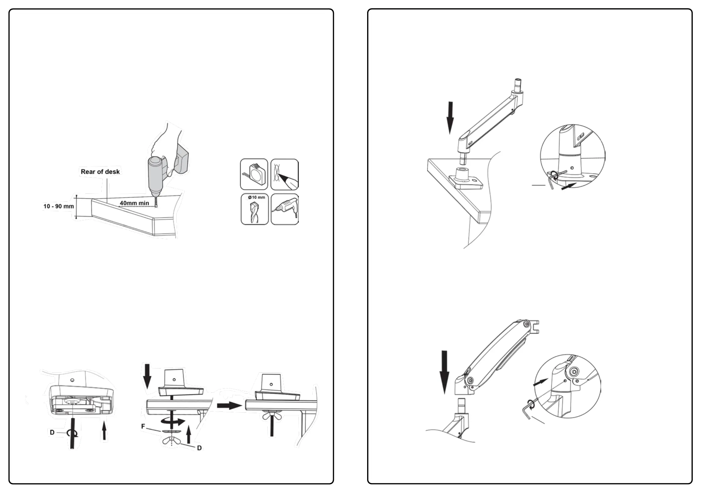
1b - Through the Desk Installation
1. Locate and position where you want the monitor arm base to sit on your desktop/work-surface. 40mm
minimum is needed from the rear of the desk so the monitor arm base makes full contact with the
desktop/work-surface - see Diagram ‘F’.
2. Measure and mark out with a pencil where you want the hole and drill the hole using a 10mm drill bit.
Please note: If you are mounting heavy screens on this monitor arm please evaluate what
desktop/work-surface you are mounting it to. (Example: Wooden surfaces like chipboard or MDF
are compressed high density boards and are less likely to cause marks or indentations. Natural
wooden surfaces are softer (not compressed) so you may consider adding protection.
Diagram ‘F’
3. Fix the threaded bolt (D) to monitor arm base with 4x full turns - see Diagram ‘G’.
4. Pass the threaded bolt through the hole made in the previous step and add clamp plate (F) and butterfly
nut (D) and tighten - see Diagram ‘H’.
Diagram ‘G’
Diagram ‘H’
3
2 - Monitor Arm Assembly
1. Take the lower arm (2) and slot the male connector into the female connection on the monitor base (3)
making sure it is fully inserted (please ensure you have this the correct way up) - see Diagram ‘I’.
Use the 3mm Allen key (E) and tighten the grub screw to lock the lower arm in place.
E (3mm)
Diagram ‘I’
2. Take the upper arm (1) and slot the female connector onto the male connection on the lower monitor arm
making sure it is fully inserted - see diagram ‘J’. Use the 3mm Allen key (E) and tighten the grub screw to lock
the upper arm in place.
Diagram ‘J’
E (3mm)
4
 Loading...