EasyManua.ls Logo

Invision MX900 - User Manual

Invision MX900
4 pages
Print Icon
To Next Page IconTo Next Page
Loading...
English
Invision MX900
Ergonomic Gas Assisted Dual Monitor Arm
Instruction Manual
VESA Compliance 75x75mm & 100x100mm
Recommended Screen Sizes 22” - 32”
Integrated Cable Management
Load Capacity 3 - 12kg (6.6 - 26.5lbs) single
To receive large format PDF instructions please email
help@InvisionTechnology.co.uk
Parts List: Tools List:
Important:
1. Check the box contains all the items in the Parts List.
2. Check the screens VESA mounting measurements and
monitor weight.
3. Please read the instructions fully and plan how to mount
your monitor.
4. You may need additional tools: A drill will only be needed
if you are bolting it through a desk, the screwdriver is used
for removing the cable management.
For more information visit www.InvisionTechnology.co.uk
WARNING!
Severe personal injury and property damage can result from improper installation or assembly. Please read the following warning carefully before beginning.
If you do not understand the instructions or have any concerns or questions please contact us or a competent installer.
Do not install or assemble if the product or hardware is damaged or missing. If you require replacement parts, please contact us at Invision for assistance.
This product fits most VESA compliant 22”-32” LCD/monitors to a maximum weight of 12kg (26.5lb).
For safe installation, the desk you are mounting it to must support minimum 3 times the weight of the total load (the mount, the monitor and all accessories weight).
Do not use this product for anything other than the original design purpose.
This product contains moving parts, please use with caution.
When installing the monitor take care not to damage electrical wiring or power source.
Important – mains and data cables must be free from twisting and/or shearing.
The manufacturer disclaims any liability for the modifications, improper installation or installation over the specified weight range. The manufacturer will not be liable for any damages arising from the use of,
or inability to use the product.
This product is designed for indoor use only, use of this product outdoors could lead to product failure and severe personal injury.
This product contains a high pressure gas piston This mechanism is not user serviceable and any interference could result in injury or damage. Please dispose of with caution.
In order to ensure the performance of the gas piston it is recommended to fully extend the arm several times per month.
Lets Get Started!
If you require assistance please contact us at: help@InvisionTechnology.co.uk
V20220218
1
Letters and numbers in ( ) are referred to in the Parts List
1. Clamp Installation
1. Secure clamping plates (3) to base (5) with bolts (C) using 4mm Allen key (F) and tighten – see
Diagram ‘A’.
2. Slide clamp (4) over clamping plate (3) and straighten to lock into place. Repeat with the 2nd clamp and
clamping plate – see Diagram ‘B’.
Diagram ‘A Diagram ‘B’
3. Measure the thickness of your desk, adjust the height of your clamps so when tightening the clamps
have enough thread on them to secure to desktop – see Diagram ‘C’.
4. Secure base assembly to the desktop making sure base is in full contact with the face of the desktop
and cables run through the back of the base – see Diagram ‘D’.
Please note:
If you are mounting heavy screens on this monitor arm please evaluate the desktop/ work-surface
you are mounting it to. (Example: Wooden surfaces like chipboard or MDF are compressed high
density boards and are less likely to cause marks or indentations. Natural wooden surfaces are
softer (not compressed) so you may consider adding protection.
Diagram ‘C’ Diagram ‘D’
2
Question and Answer IconNeed help?

Do you have a question about the Invision MX900 and is the answer not in the manual?

Summary

Clamp Installation

Secure Clamping Plates

Attach clamping plates to the base using specific bolts and Allen key for tightening.

Slide and Lock Clamp

Slide the clamp over the clamping plate and straighten to lock it securely in place.

Adjust Clamp Height

Measure desk thickness and adjust clamp height for sufficient thread contact.

Secure Base Assembly

Ensure base has full contact with the desktop and cables route through the back.

Through the Desk Installation

Position and Mark Hole

Locate arm base, ensure 50mm clearance from desk rear, mark hole for drilling.

Drill Desk Hole

Drill a 10mm hole at the marked location for the threaded bolt.

Fix Threaded Bolt

Attach the threaded bolt to the monitor arm base using four full turns.

Secure with Plate and Nut

Pass bolt through hole, add securing plate and butterfly nut, then tighten.

Monitor Arms Assembly

Attach Lower Monitor Arm

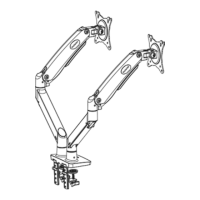
Slot male connector of lower arm into base, tighten grub screw with Allen key.

Attach Upper Monitor Arm

Slot female connector of upper arm onto lower arm's male connection, tighten grub screw.

Attaching Face Plate to Monitor Arm

Align Face Plate

Slot face plate connector between upper arm prongs, aligning mounting holes.

Secure Face Plate

Use bolts and washer to attach face plate to upper arm, tighten with Allen key.

Adding Cables to the Monitor Arms Cable Management

Release Upper Cable Tray

Remove bolt from upper arm tray, slide it down to release.

Route Cables in Upper Tray

Add cables with enough slack for monitor swivel or rotation.

Reattach Upper Cable Tray

Slide tray into notch, push upwards, and re-secure with bolt.

Release Lower Cable Tray

Gently push down on top hole of lower tray to release pins from upper arm.

Route Cables in Lower Tray

Add cables with sufficient slack between arms and equipment.

Reattach Lower Cable Tray

Place tray in lower notches, press upper pins to locate into top holes.

Mounting the Monitor

Check VESA Mount Size

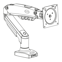
Measure VESA mounting hole distance on monitor screen.

Attach Monitor Bolts

Screw bolts into top VESA holes, leaving space for hanging.

Hang Monitor

Carefully lift the monitor and hang it onto the attached face plate.

Secure Bottom Bolts

Fit the bottom two bolts into the face plate and tighten all monitor bolts.

Setting Monitor Arm Tension

Adjusting Upwards Screen Movement

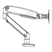
Tighten tension by turning set screw clockwise for screens moving upwards.

Adjusting Downwards Screen Movement

Loosen tension by turning set screw anti-clockwise for screens moving downwards.

Adjusting the Tilt Angle

Tighten Tilt Adjustment

Turn adjustment bolt in plus direction with Allen key to tighten tilt.

Rotational Features

Monitor Rotation

Rotate screen 360 degrees for portrait or landscape mode.

Invision MX900 Specifications

General IconGeneral
BrandInvision
ModelMX900
CategoryRacks & Stands
LanguageEnglish

Related product manuals