4. Put your finger into the top hole of the lower cable management tray – see Diagram ‘O’. With gentle
pressure push down to release the pins from the two holes on the top of the lower arm.
5. Add cables as shown in Diagram ‘P’ ensuring there is enough slack between the upper and lower arms
and your equipment.
6. Replace the cable management tray into the lower notches first. Then with gentle pressure press on the
upper pins and locate the tray into the top holes on the lower arm – see Diagram ‘Q’. Repeat on second
monitor arm.
Diagram ‘O’ Diagram ‘P’ Diagram ‘Q’
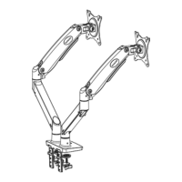
5. Adding Cables to the Monitor Arms Cable Management
If you are using cables to connect your monitor to your PC please ensure you have enough cable
length to travel the distance between your equipment before installation.
1. Remove the bolt from the upper arm cable management tray using a Philips screwdriver and slide the tray
downwards from the notch to release it - see Diagram ‘L’.
2. Add cables as shown in Diagram ‘M’ ensuring there is enough slack for the monitors to swivel or rotate.
3. Replace the cable management tray into the notch and push it upwards. Locate the bolt into the screw
hole and tighten with a Philips screwdriver – see Diagram ‘N’. Repeat on second monitor arm.
Diagram ‘L’ Diagram ‘M’ Diagram ‘N’
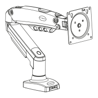
4. Attaching Face Plate to Monitor Arm
1. Take a face plate (6) and slot the face plate connector between the prongs located on the upper arm
making sure the holes are aligned – see Diagram ‘J’.
2. Use bolt and washer (G) to secure face plate to upper arm and use 5mm Allen key (F) to tighten –
see Diagram ‘K’. Repeat to the second upper arm.
Diagram ‘J’ Diagram ‘K’
(5mm)
Face plate
5
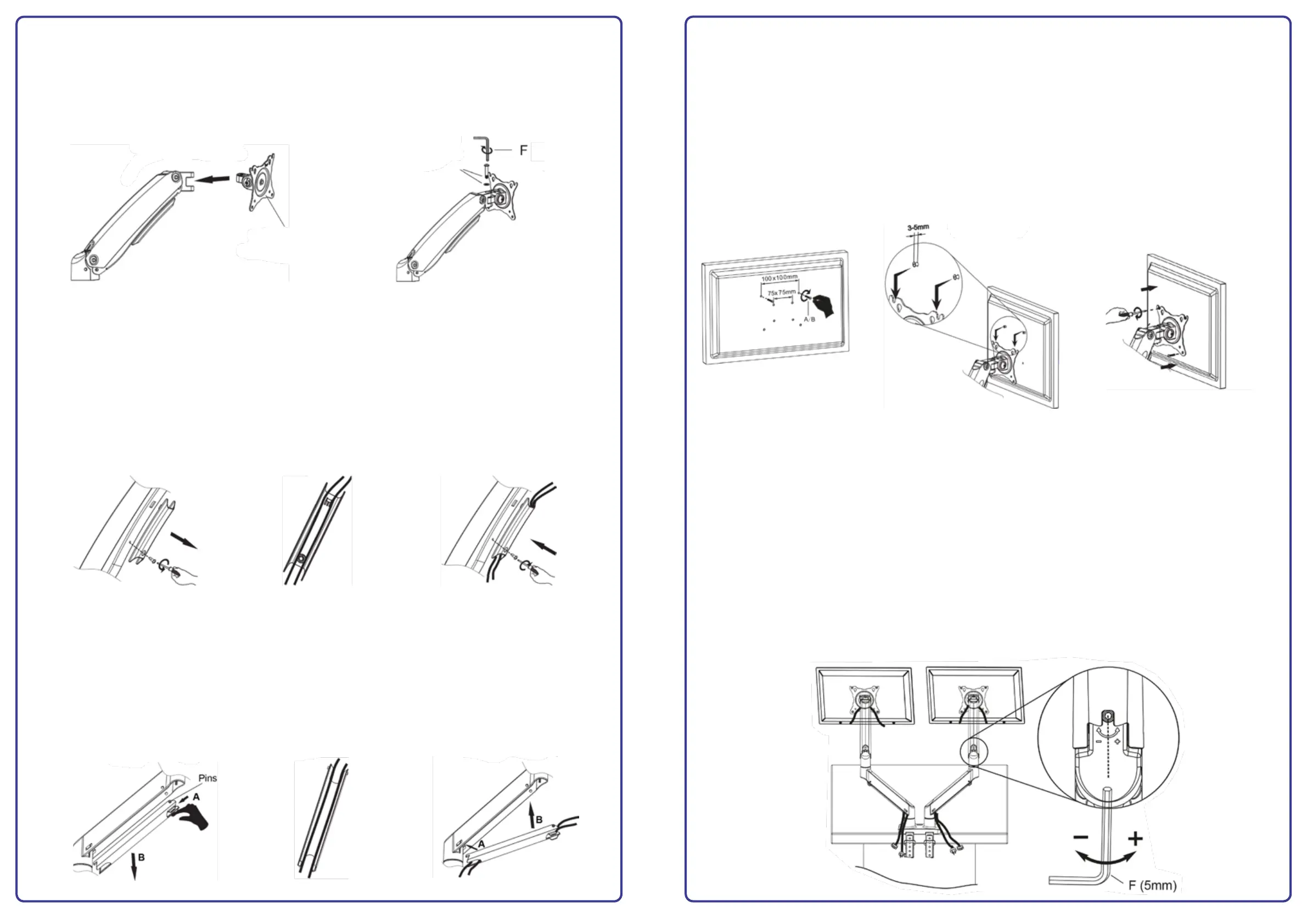
6. Mounting the Monitor
Please note: It is advisable to do both steps 6 and 7 with one monitor at a time.
1. Check monitor VESA by measuring the distance between the mounting holes on the back of the screen –
this is where bolts A or B will fit.
2. Screw two bolts into the top two holes on the back of the monitor using 5mm bolts (A) or (B) and tighten
in three turns leaving room between the bolt head and rear of screen for hanging the monitor – see
Diagram ‘R’.
3. Carefully lift monitor and hang onto the face plate see Diagram ‘S’.
4. Fit the bottom two bolts into the face plate and tighten all the bolts – see Diagram ‘T’.
Diagram ‘R’ Diagram ‘S’ Diagram ‘T’
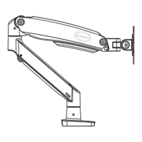
7. Using Your Invision MX900 Ergonomic Monitor Arm
Setting the tension of the monitor arms to balance the weight of your monitors
Once fitted the screen may rise or lower depending on the monitor’s weight. From minimum
tension to maximum tension there are 22x full rotations. When making adjustments make one full
turn of the Allen key (F) and check by depressing the upper arm to see if the monitor is
balanced evenly.
1. If the screen moves upwards of its own accord then adjust the tension using the 5mm Allen key (F)
and wind the set screw in the minus direction (clockwise).
2. If the screen moves downwards of its own accord then adjust the tension using the 5mm Allen key
and wind the set screw in the plus direction (anti-clockwise) – see Diagram ‘U’.
Continue to make adjustments until the monitor weight feels equal in both directions to the tension
of the monitor arm. It should then hold in place when positioning the monitor and will not rise or
lower of its own accord.
Diagram ‘U’
6
 Loading...