EasyManuals Logo

Inxpect LBK System Installation Instructions

Inxpect LBK System
To Next Page IconTo Next Page
To Previous Page IconTo Previous Page
Page #17 background imageLoading...
Page #17 background image
EN
SAF-MI-LBK-SBV-multi-v2.0-print-26000041 |© 2020-2021 Inxpect SpA Installation instructions 17
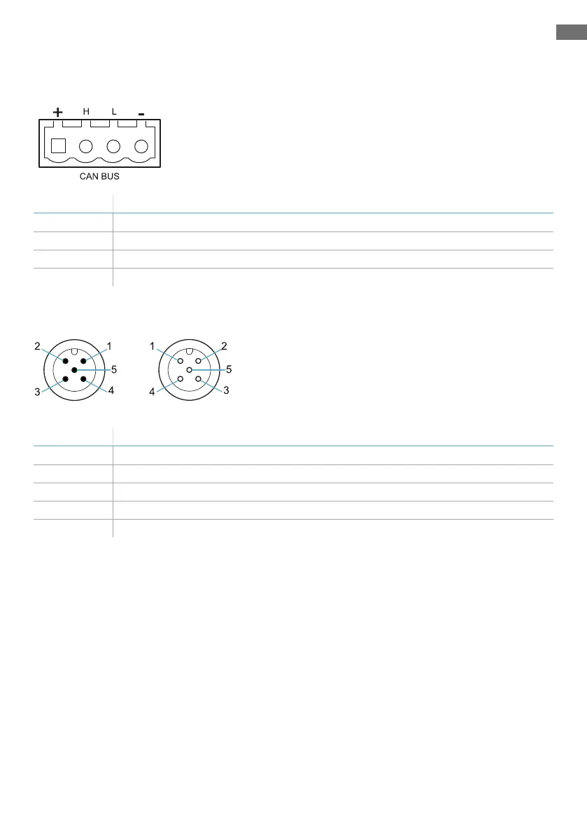
Terminal blocks and connectors pin-outs
LBK-C22 and ISC-B01 CAN bus terminal block
Symbol Description
+ + 12 V dc
H CAN H
L CANL
- GND
Note: the operating temperature of the cables must be at least 80 °C for LBK-C22 and 70 °C for ISC-B01.
LBK-C22 and ISC-B01 M12 CAN bus connectors
Male connector Female connector
Pin Function
1 Shield, to be connected to earth circuit power supply terminal block of the controller.
2 + 12 V dc
3 GND
4 CAN H
5 CANL

Other manuals for Inxpect LBK System

Questions and Answers:

Question and Answer IconNeed help?

Do you have a question about the Inxpect LBK System and is the answer not in the manual?

Inxpect LBK System Specifications

General IconGeneral
BrandInxpect
ModelLBK System
CategorySafety Equipment
LanguageEnglish

Related product manuals