EN
20 Installation instructions SAF-MI-LBK-SBV-multi-v2.0-print-26000041 |© 2020-2021 Inxpect SpA
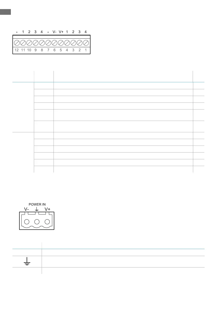
ISC-B01 digital inputs and outputs terminal block
Note: facing the controller in such a way that the terminal block is top left, number 12 is the nearest to the
controller corner.
Terminal
block
Symbol Description Pin
Digital In 4 Input 2, Channel 2, 24 V dc type 3 - INPUT #2-2 1
3 Input 2, Channel 1, 24 V dc type 3 - INPUT #2-1 2
2 Input 1, Channel 2, 24 V dc type 3 - INPUT #1-2 3
1 Input 1, Channel 1, 24 V dc type 3 - INPUT #1-1 4
V+ V+ (SNS), 24 V dc for diagnostics of the digital inputs (mandatory if at
least one input is used)
5
V- V- (SNS), common reference for all digital inputs (mandatory if at least
one input is used)
6
Digital
Out
- GND, common reference for all digital outputs 7
4 Output 4 (OSSD4) 8
3 Output 3 (OSSD3) 9
2 Output 2 (OSSD2) 10
1 Output 1 (OSSD1) 11
- GND, common reference for all digital outputs 12
Note: the cables used must have a maximum length of 30 m (98.4 ft) and the operating temperature must
be at least 80 °C.
Note: use only copper wires with a minimum gauge of 18 AWG and a torque of 0.62 Nm (5,5 lbs in).
ISC-B01 power supply terminal block
Note: front view of connector.
Symbol Description
V- GND
Earth
V+ + 24 V dc
Note: the operating temperature of the cables must be at least 70 °C.
Note: use only copper wires with a minimum gauge of 18 AWG and a torque of 0.62 Nm (5,5 lbs in).