2
14140 NE 200th St.
Woodinville, WA 98072
1.425.398.8282
www.ioline.com
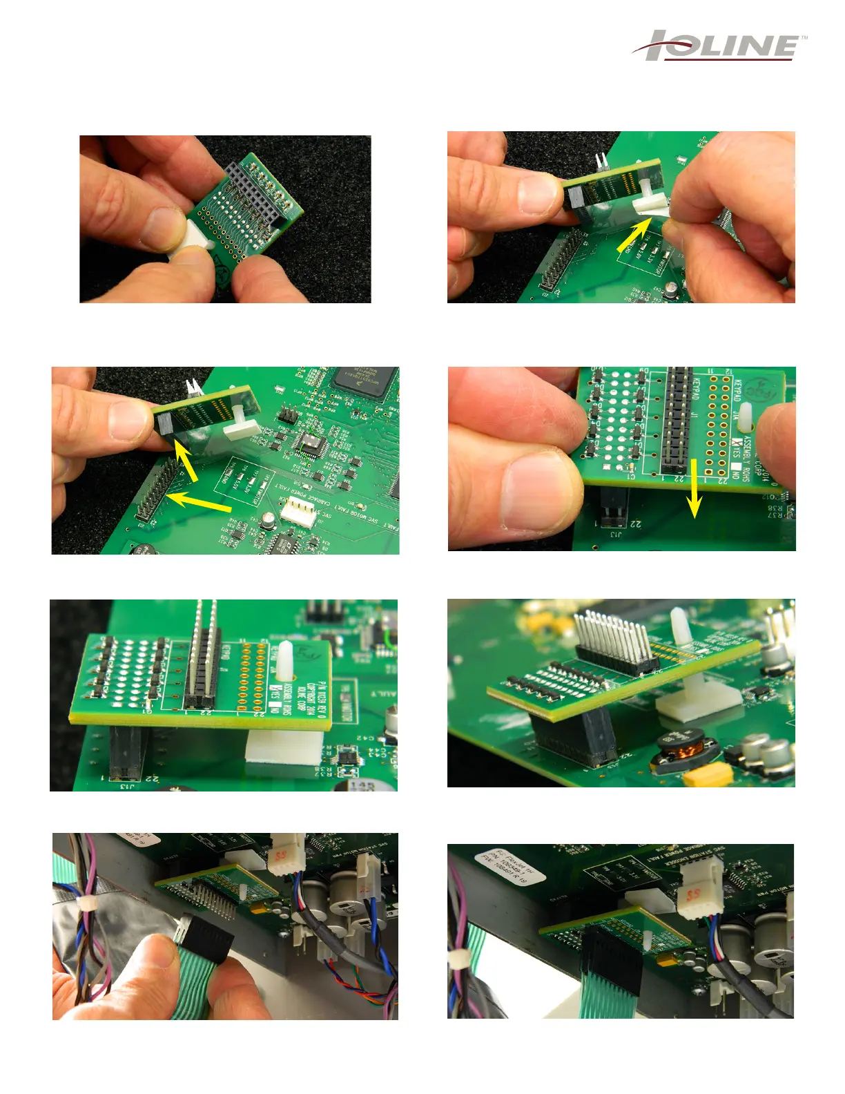
Step 9: While wearing the anti-static wrist strap, rmly
press the white stabilizer stand through the hole in the
EMI board until you hear and feel a solid click. NOTE:
This will take a little effort to press in.
Step 10: The white plastic stabilizer has a piece of
protective lm over the adhesive tape. You need to
remove this before placing it on the board (arrow).
Step 11: The EMI board is ready to place on the main
board. You must align all the prongs for correct inser-
tion (arrows).
Step 12: Once aligned, press down until you no longer
can see the silver metal prongs. Step 13.
Step 13: This photo shows the EMI board correctly
pressed down upon the main board.
Step 14: Another angle showing how the EMI should
appear. No prongs seen, and the stabilizer with the
adhesive pressed onto the board.
Step 15: Once the new EMI suppressor is attached,
you can re-attach the green keypad cable.
Step 16: Shown is how the EMI and the keypad cable
should appear.
NOTE: For steps 10-14, the main board was
removed for visibility. DO NOT do this for your
installation.