4
iOptron Corp. | 6E Gill Street | Woburn, MA 01801 USA | (781) 569-0200 | www.iOptron.com
clockwise to disengage the worm from the worm
wheel. Turn the Gear Switch counterclockwiseto
engagethewormtowormwheel,asindicatedonthe
mount.Youmayfeela“click”whenthegearmeshed.
CAUTION:ThebalancingprocessMUSTbedonewith
GearSwitchattheDisengageposition!Otherwiseit
mightdamagethewormsystem.
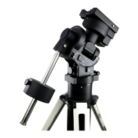
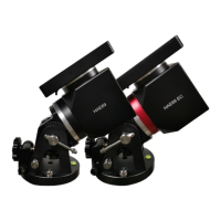
With the corresponding Gear Switch disengaged,
balance in DEC axis by moving the scope with
accessories back and forth in the mount saddle or
withinthescopemountingrings.Balancethe
assemblyinR.A.axisbymovingCWalongitsshaft.
Only balance one axis at a time and start with the
DECaxisfirst.Doublecheckthemounttomakesure
boththeRAandDECaxesarebalanced.
Return the mount to the Zero Position after
balancing; i.e., the CW Shaft points to ground, and
thetelescopetipisatitshighestposition.
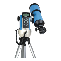
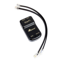
7. ConnectingCables:Plugina12VDCpowersupplyto
theDC12VPOWERsocket.ConnecttheGo2Nova
®
8407HandControllertotheHBXportonthemount
sidepanel.
RefertothefullUser’sManualonhowtousethe
cablemanagementsystem.
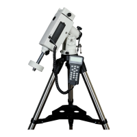
8. SettingGearSwitchPosition:SetbothGearSwitches
toengagedpositionsafterbalancingthemount.To
makesurethegearsaremeshedproperly,gentlyturn
the Gear Switch counterclockwise (CCW)untilyou
justfeelthestop,butneverovertightening.More
adjustmentmaybeneededasdescribedbelow.
Turnthemountpoweron.Press9buttononhand
controller to change the slew speed to MAX. Press
thearrowbuttontocheckthegearmeshing.Ifthe
mountmotorhas“grinding”sound(whichisnot
harmful) while slewing, the gear switch is too tight.
Release1/16to1/8turn(clockwise,CW)andcheckit
again.IfthereisexcessplayineitherRAorDECaxis,
thegearandwormisnotproperlymeshed.Turnthe
GearSwitchmoreCCW.Youmayneedtoreadjustthe
gearswitchfordifferentpayload.
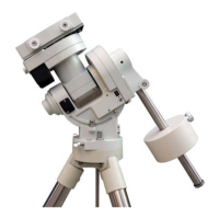
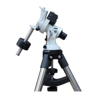
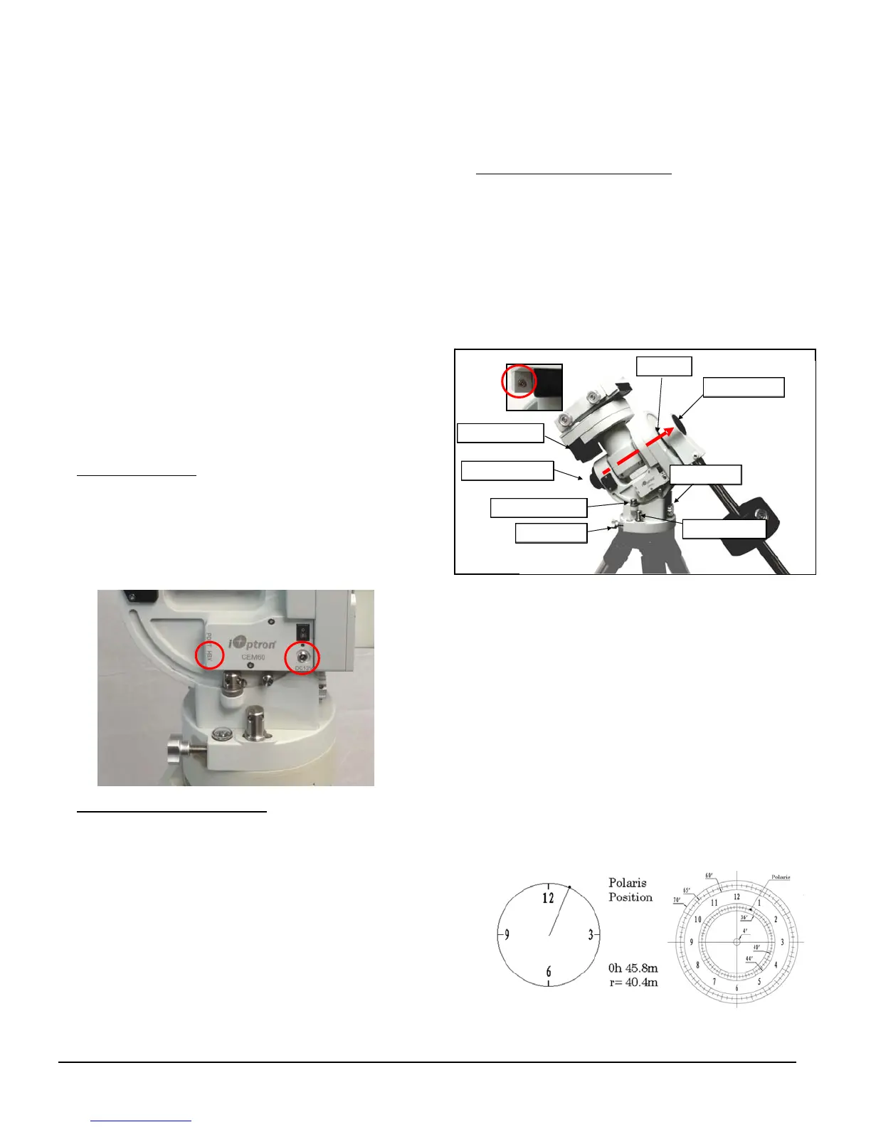
9. Performing Polar Alignment:RemovebothPolar
Scopeandpolaraxiscovers.Lookthroughthepolar
scopetolocatePolaris(orSigmaOctantisatsouthern
hemisphere). Slightly loosen the Azimuth Locking
Nuts and Latitude Locking Clamps. Use the two
AzimuthAdjustmentKnobsonthesidetocenterthe
pole star in the azimuth direction. Use the Latitude
AdjustmentKnobforthelatitudeadjustment.Tighten
thenutsandclampsafteradjusting.
QuickPolarAlignment
Fastandaccuratepolaralignmentcanbeperformed
withiOptron’sAccuAligning
TM
PolarScope.
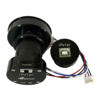
(1) Connect the Polar Scope illumination LED to the
ReticlesocketlocatednexttoDECdriveunit(see
insert above). Turn the mount power on. Use
Hand Controller (“Settings” => “Polar Scope
Brightness”)tosettheilluminationintensity.
(2) Use Hand Controller (MENU=>“Alignment” =>
“Position of Polaris/SigmaOct”)todisplaythePolaris
PositionontheLCDscreen,asindicatedbelow.For
example,June22,2014,20:19:42inBoston,US(long.
W71°08’50” and lat. N42°30’32”, UTC ‐300 min,) the
PolarisPositionis0h45.8mand40.4m.
DECdriveunit
Polaraxiscover
Polarscopecover
Az.adj.knob
Az.Lockingnut
Lat.lockingclamp
Polaraxis
Lat.adj.knob
LED
Socket
 Loading...