2
iOptron Corp. | 6E Gill Street | Woburn, MA 01801 USA | (781) 569-0200 | Toll Free (866) 399-4587 | www.iOptron.com
STOP!!! Carefully read this Guide BEFORE setting up and using the equipment! Worm
system damage due to user operation error will not be covered by warranty.
WARNING: Never disengage Gear Switches without holding the mount firmly! Personal injury
and/or equipment damage may happen.
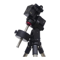
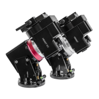
1. Remove mount head from package: The RA axle is
locked by an Allen wrench (blue circle). Make sure it
is inserted all the way in. Check the R.A. and DEC
Gear Switches and turn them to unlocking position
before removing it from the box.
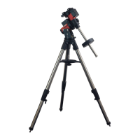
2. Set up tripod: The mount has a 102mm base. Thread
the Alignment Peg onto the tripod head, on top of a
tripod leg or between two legs depending on the
latitude. Insert the Accessory Tray through the center
rod and secure the setup by tightening Locking Knob
from underneath.
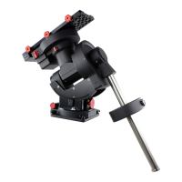
3. Attach mount head: Retract the 2x Azimuth (Azi)
Adjustment Screws from both sides to leave ample
space for the alignment peg to be fitted in between
the 2x Azi Adjustment Screws. Remove the 2x Azi
Locking Screws from the mount base. Secure the
mount head by tightening the Azi Locking Screws into
the M6 holes on the tripod. After tighten the Azi
Locking Screws, store the Allen wrench at the bottom
of the mount altitude support.
Rotate the mount head to normal position.
Level the mount by adjusting the tripod legs. Use the
build-in Bubble Level Indicator or an external leveler
for this purpose.
 Loading...