6
2.4. SkyTracker
TM
Camera Mount Assembly
NOTE: The SkyTracker
TM
mount is a precision astronomical instrument. It is highly
recommended that you read the entire manual and become familiar with the nomenclature and
functions of all components before starting the assembly.
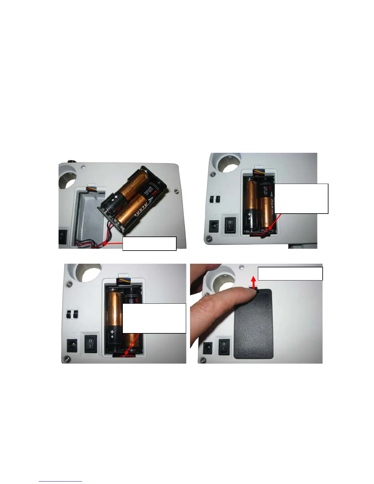
STEP 1. Install batteries
The battery compartment is located at the back of the SkyTracker
TM
mount (Figure 4). Lift the
battery compartment cover and gently pull out the battery holder from the compartment. Insert 4 fresh
AA batteries (not included) into the holder (Figure 5a). Since it is a tight fit, you may find that you
cannot put the battery cover back due to the wires. Straighten the battery holder wires, slide the
battery holder back into the battery compartment and leave the wires outside, as shown in Figure 5b.
Then push the battery holder wires down into the battery compartment, as shown in Figure 5c. Place
the battery cover back onto the battery compartment and push the cover hook up to secure the
battery cover (Figure 5d)
(a) (b)
(c) (d)
Figure 5. Install batteries
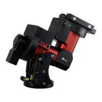
STEP 2. Attach the SkyTracker
TM
Mount
Carefully thread the SkyTracker
TM
mount onto your tripod and make sure it is securely
tightened. The mount base has a 3/8” threaded socket. If your tripod only has a 1/4” threaded post, a
1/4” to 3/8” tripod adapter screw (not included) is needed, as shown in Figure 6.
Battery wires
Leave wires
outside battery
compartment
Push wires down
into battery
compartment
Lock battery cover