2 ID-299 Iss 3 08/07/981ID-299 Iss 3 08/07/98
The Quick Guide (Part 1)
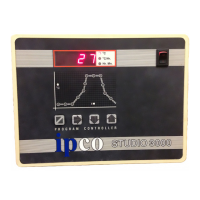
The controls and ‘Running’ a program.
This will normally show the kiln temperature in ºC.
Display When entering or amending a program other information will bedisplayed.
The three LED’s to the right of the display show the units ofthe information being displayed.
On/Off Switch This switches power to the controller.
Mimic When a program is running the progress through the firing cycle is indicated by the green LED’s in the centre of
Diagram each segment.
When entering or viewing the stored program the red LED’s indicate which part of the cycle is being displayed.
Operator KeysThese are used to Stop or Start a firing cycle and to change the stored values.
TO RUN A PROGRAM
Switch On (Or plug in) the kiln.
Switch On the controller. (The Display should light up and after a while show the current temperature.)
Check the mimic has no lights lit. (If there are Press the key to clear them.)
Press the → key to display the program number.
Press either the ↑ or ↓ key to change the program number if required.
Press the key to run the program.
On all but the single program version of the Studio 3000, ten firing programs can be stored in the controllers memory. For ease of use
the Controller pre-set programs can be used or modified to suit your requirements.
PLEASE READ THIS
This manual describes all aspects of the use of your STUDIO 3000 controller. It is split into three sections. Page one should be read by
all users as it covers important SAFETY information If you are a non technical user you are advised to fully read pages two and three
which give a pictorial view of the basic use of the controller. If you are an experienced user you should find all the information you
need under the headings shown below in the contents list. If after all this you have problems then the fault finding section should be
referred to.
CONTENTS
TOPIC Page TOPIC Page
Installation ......................................1 Event Relay ....................................5
Quick Guide....................................2 + 3 3 Zone Control................................6
At Switch ON.................................4 Electrical Connections....................7
During the firing.............................4 Option Wiring.................................8
Security Lock..................................5 Configuration..................................9
Gas Relay........................................5 Fault Finding ..................................10
Alarm Relay....................................5 Specifications..................................11
Installation
Mounting The controller should be mounted on a flat vertical surface away from the kiln, so that it cannot be affected by the
heat that will radiate during the firing of the kiln.
A removable bracket at the rear of the controller is used for fixing. Slide the mounting bracket from the rear of
the controller and fix using two No 8 countersunk screws.
Connection It is vital that all electrical installation is carried out in a professional manner.
We do not recommend DIY installation of this product.
Before using the controller ensure the ‘Sensor Type’ (Shown on the rear of the controller), and the
thermocouple in the kiln are the same.
In most instances the controller will either have a plug which matches your kiln, or will be connected by your
supplier. If a plug is fitted check that the pin layout of the plug and socket are an exact match before plugging in.
If in doubt contact your kiln supplier
Safety It is strongly recommended that where a kiln is to be fired unattended that an additional totally
independent over temperature safety system is fitted.
Ensure there is no risk of water entering the controller or its connecting leads.
If you have not bought the kiln & controller as a package be sure you have read and followed EVERY part of this
manual.
Declaration This Equipment conforms to European Standards for Electrical Interference EN50081-1 and EN50082-2 when
installed as described in this manual. (See “Electrical Connections”)
Compliance Dated 1st December 1995
Problems In the unlikely event that your controller does not perform correctly ;-
Please first refer to the “Fault Finding” Section.
Check, or get someone else to check, that your firing sequence has been correctly entered.
Contact your supplier in the first instance, since they should have knowledge of your installation which we may
not be aware of.
When contacting us please check the initial display of the instrument (See “At switch on”)
Settings for Studio 3000 MP & MPL Controllers
Program Type Slow Normal High Stoneware Porcelain Low Med High Lustre Enamel
Biscuit Biscuit Biscuit Temp Temp Temp
Glaze Glaze Glaze
Program Number - Pn.01 Pn.02 Pn.03 Pn.04 Pn.05 Pn.06 Pn.07 Pn.08 Pn.09 Pn.10
Delay Hr-Min 0 0 0 0 0 0 0 0 0 0
Ramp 1 Rate ºC/Hr 50 100 100 100 100 150 150 150 Pass Pass
Ramp 1 Temperature ºC 200 600 600 200 200 500 500 500 - -
Ramp 2 Rate ºC/Hr 250 250 250 250 150 250 250 250 125 120
Soak Temperature ºC 1,020 1,020 1,160 1,260 1,290 960 1,070 1,120 750 800
Soak Time Hr-Min 0 0-10 0 0-10 0 0-10 0 0 0 0
Ramp 3 Rate ºC/Hr Pass Pass Pass Pass Pass Pass Pass Pass Pass Pass
 Loading...