SECTION III
Operation
Page 3.18
BP+2.9X
11/95
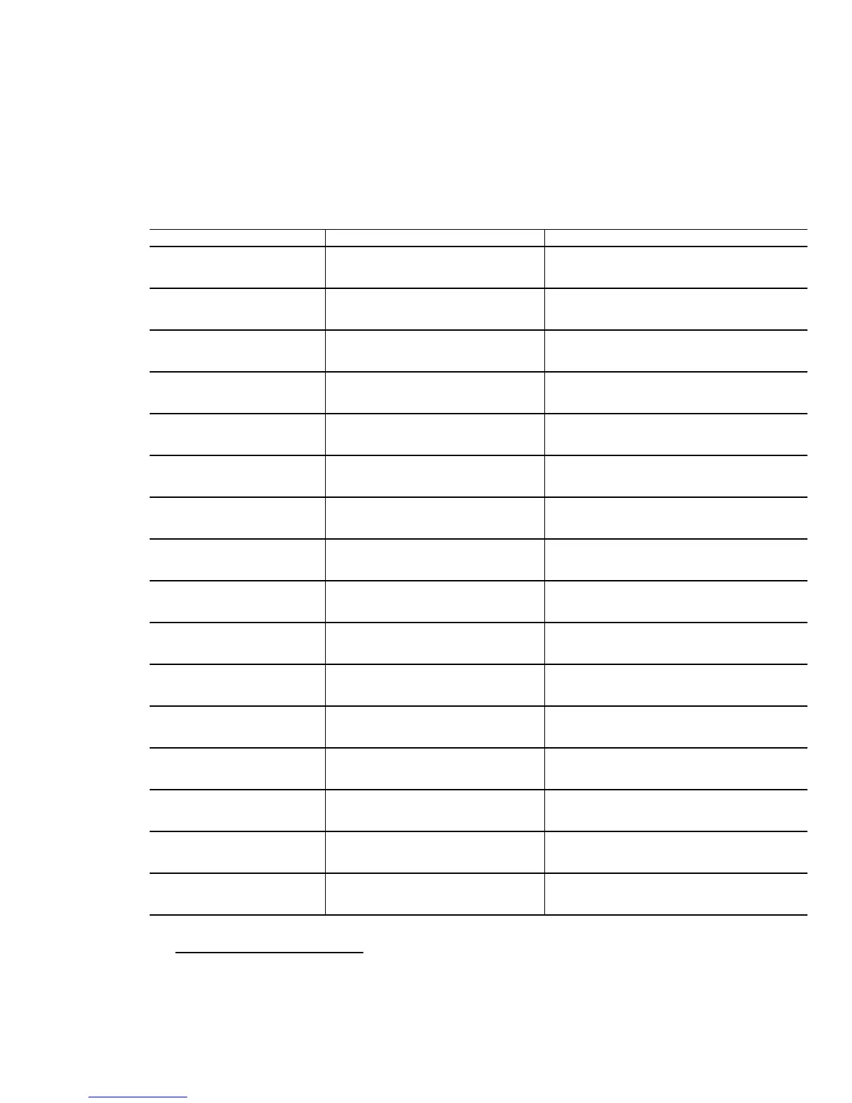
Table 3.2 (continued)
Screen Message Description Corrective Action
inv bIn fusB Inverter fuse B blown Test/replace inverter fuses on A2 power
assembly.
inv bIn fusC Inverter fuse C blown Test/replace inverter fuses on A3 power
assembly.
inv PS fail Power supply failure Test/replace inverter drive boards on A1,
A2and A3 power assemblies.
inv PS norml* Power supply normal No action required
inv Iocked* lnverter phase locked No action required
inv not lock Inverter not phase locked Verify UPS input voltage and frequency.
inv ovr tmpA Inverter over temperature. phase
A
Verify cooling fans are operating on A1
power assembly.
inv ovr tmpB Inverter over temperature, phase
B
Verify cooling fans are operating on A2
power assembly.
inv ovr tmpC Inverter over temperature, phase
C
Verify cooling fans are operating on A3
power assembly.
inv norm tmp* Inverter temp. normal No action required
inv cur norm* Inverter current normal No action required
inv OC shtdn Inverter shut down -over current Remove some of the load
inv OT shtdn Inverter shut down -over
temperature
Room is too not or fan failure
inv cur limt Inverter current limit Reduce load on UF’S
xfer enabled* Transfer enabled No action required
Rexfr enabled* Retransfer enabled No action required
* Not an alarm condition.