www.iprosecu.com
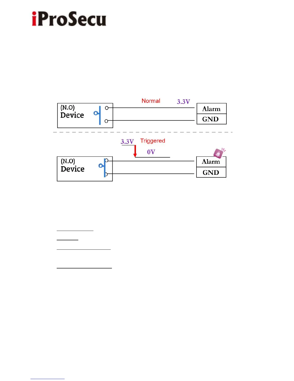
If you select "N.C" in "Input sensor setting", when the external device or circuit
mare connected to Alarm and GND pins, the camera input alarm is triggered,
and then camera will execute the action the user has set, for example, sending
snapshot to E-mail address.
c. I/O PIN definition
• GND (Ground): Initial state is LOW
• Alarm In: Max. 50mA, DC 3.3V
• N.C. (Normally Close): Max. 1A, 24VDC or 0.5A, 125VAC
• COM (Common)
• N.O. (Normally Open): Max. 1A, 24VDC or 0.5A, 125VAC
2. I/O Setup
a. Click I/O Setting from the system setup page via IE, and check “Out1” to
enable I/O signal.