7
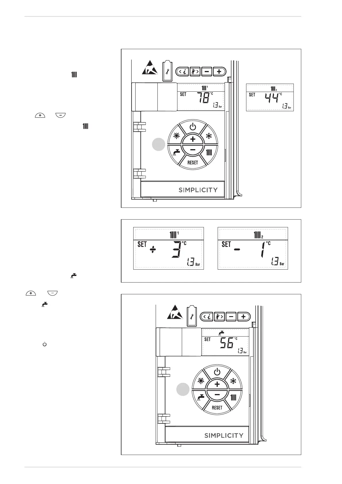
To set the temperature of the water for
heating, press the key of the controls
(2). The first time the
key is pressed, the SET of heating circuit
1 is selected. The second time it is
pressed, the SET if second zone fitted is
selected. The display will be as shown in
the figure. Change the values with the
key
and
.
Standard visualisation will return to the
display by pressing the key
again, or
after 10 seconds if no key is pressed.
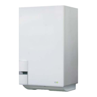
If an external sensor is installed, the
value of the output temperature is
automatically chosen by the system,
which quickly adjusts the environmental
temperature on the basis of the external
temperature.
If you wish to change the value of the
temperature, increasing or decreasing
that calculated automatically by the
electronic card, proceed as indicated in
the preceding paragraph.
The level of various correction of a value
of temperature proportional calculated.
The display will be as shown in fig. 25/a.
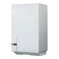
To set the desired temperature of the
D.H.W., press the key of the controls
(pos. 2). The display will be as shown in
the figure. Change the values with the key
and
.
The display will return
to the standard visualisation by pressing
the key again, or after 10 seconds if
no key is pressed.
In the case of a short absence, press
the key
of the controls (pos. 2). The
display will be as shown in the fig. 24.
In this way, leaving the electricity and
the fuel supply connected, the boiler
is protected from frost and from the
pump becoming jammed. If the boiler
is not used for a prolonged period, it is
advisable to disconnect the electricity
supply, by switching off the main switch
of the system, and to close the gas tap
and, if low temperatures are expected, to
completely empty the hydraulic circuits
to avoid pipes being broken by the
formation of ice in the pipes.
When there is a functioning error, the
display shows an alarm and the blue
APRE
2
2
2
Circuito
riscaldamento 2
Circuito
riscaldamento 3
(impianto tre
zone)
Fig. 25
APRE
2
2
2
Circuito
riscaldamento 2
Circuito
riscaldamento 3
(impianto tre
zone)
APRE
2
2
2
Circuito
riscaldamento 2
Circuito
riscaldamento 3
(impianto tre
zone)
Fig. 26
Fig. 25/a