27
Assembly Instructions - 72” (cont.)
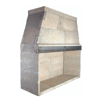
FIGURE 51
FIGURE 52
FIGURE 53
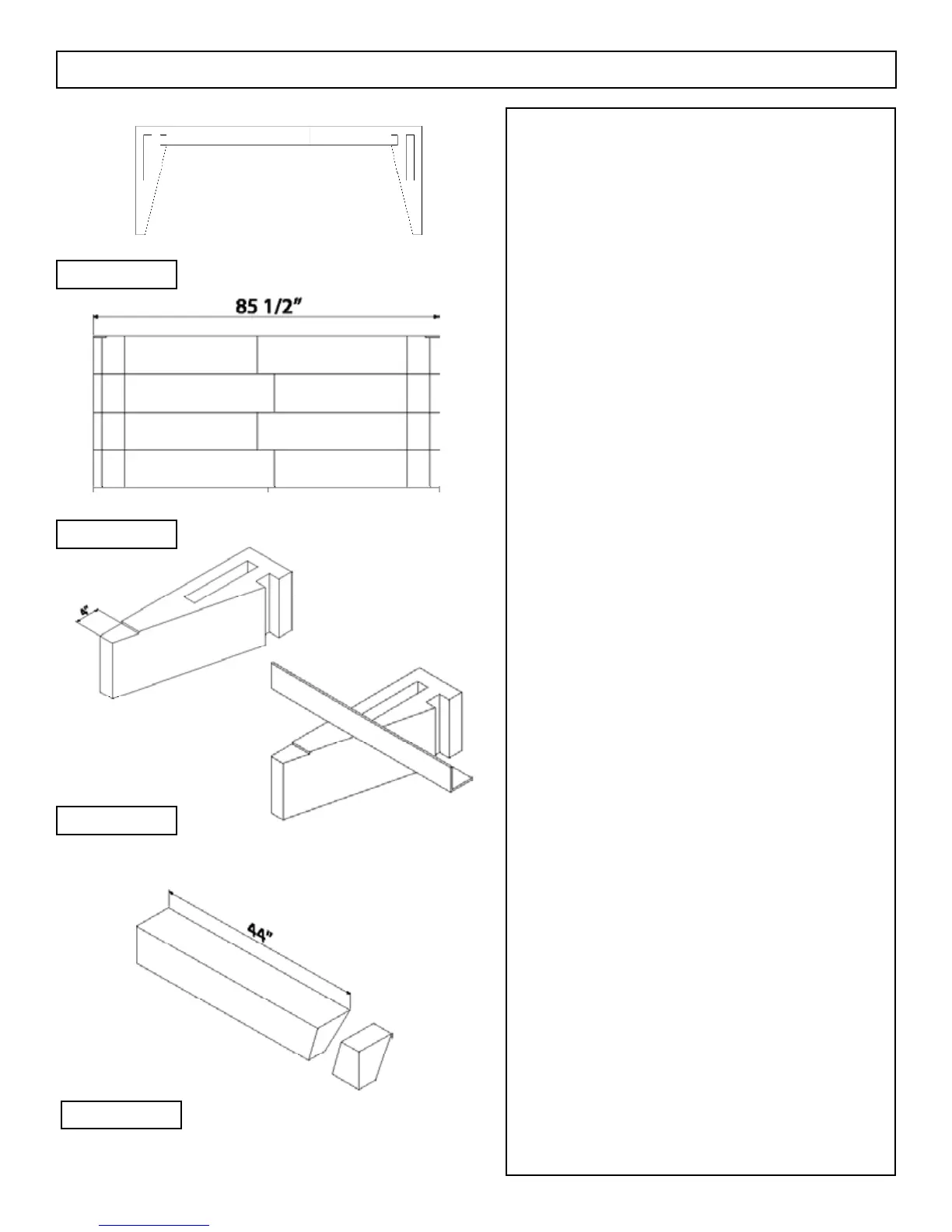
FIGURE 54
Step 6: Continue stacking the remaining three courses of
back wall. Be sure to reverse the positions of the 38 1/2”
M67 and the 34-1/2” M67 in each successive course. In
this way, the butt joint where the two M67 components
meet are staggered from course to course.
The overall width dimension at the back of the
rebox should be 85 1/2” (Figure 52).
Step 7: Steel angle of 4” x 6” x 5/16”, one each required,
85 1/2” long.
A 4” x 6” x 5/16” steel angle needs to span the
top of the MAGNUM Model 72 rebox opening.
This steel angle sits on top of the uppermost side
wall component with the four inch leg in the horizontal
position. To avoid a thickness problem with the placement
of the steel angle it is necessary to cut a notch in the top
side wall component where the angle is to sit.
This notch should be cut approximately 5/16”
deep. The notch should start at the front face of the side
wall component (at both the left and right hand walls) and
run to a point four inches back toward the rebox
(Figure 53).
The steel angle sits in this notch. The six inch
leg of the steel angle is in the vertical position and is to
be located in alignment with the front of the rebox. The
ends of the steel angle should not protrude beyond the
outer rebox side walls. (Figure 53)
Mortar between the steel and the notch in the top
of the side wall is not needed.
Step 8: Damper support (front & rear), part M69, four
required, to be eld cut to t.
Bevel cut one end of each of two M69 damper
supports to 44” in length from the long point of the bevel
cut to the un-cut square end. The long point of the bevel
cut is to be at the top of the damper supports (Figure 54).
For best results a 15˚ bevel angle is suggested.
Step 9: Bevel cut one end each of two M69 damper sup-
ports to 41 1/2” with the long point of the bevel at the
bottom of the damper support. The bevel angle must be at
the same angle in this case, 15˚ - to match with the bevel
angle of the other damper supports already cut in Step 8
(Figure 55).
Step 10: Set the cut damper supports along the front and
along the rear of the rebox using one of each of the cut
pieces (one with the long point at the top of the piece
and one with the long point at the bottom of the piece)
together as pairs.
 Loading...


