2"6"
4" 2"
BEARING
2"6"
WOOD (FLAMMABLE)
SHEATHING
MIN. CLEARANCE
MIN. CLEARANCE
BRICK
VENEER
WOOD (FLAMMABLE)
SHEATHING
MASONRY VENEER
4x6 STEEL L
MASONRY BEYOND
AIR SPACE
MORTAR JOINT
38
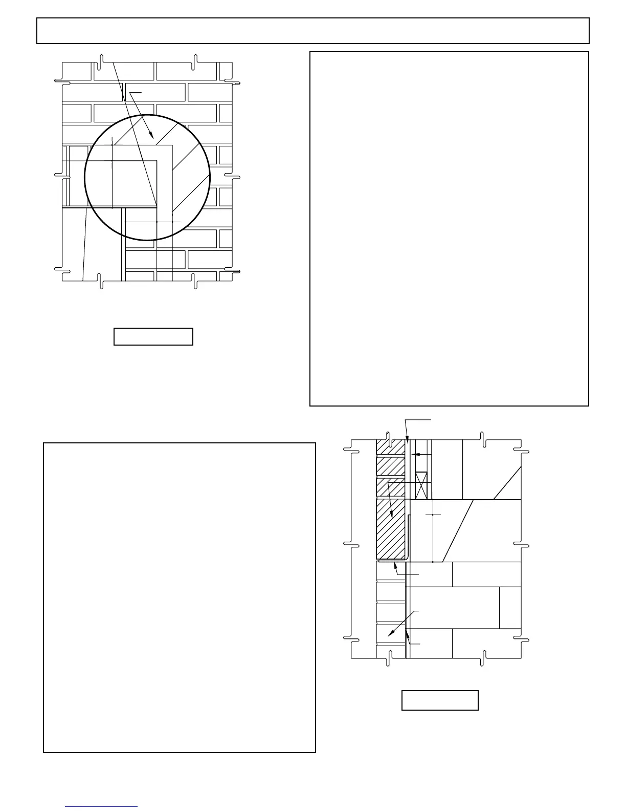
Masonry Veneer Construction Details
Brick, stone or other masonry veneer nished fronts to
MAGNUM replaces are possible. Special attention is required
with regards to:
(1) the placement of the proposed masonry
veneer facing and its interface with the MAGNUM re brick lin-
ing, and
(2) the masonry veneer and clearance to combustible framing and
sheathing from any steel “L” support used in the masonry veneer
around the front of the MAGNUM unit behind the veneer facing.
Any proposed brick, stone or other masonry veneer
facing must have sufcient foundation to support the full weight
of the veneer work. This may require review by a local structural
engineer prior to construction.
The veneer facing, when installed, must present a tight
seal with the leading edge - the room edge - of the MAGNUM
re brick lining at the sides of the MAGNUM rebox opening.
(Figure 83)
A steel “L” will need to span the top of the nished
replace opening to carry the masonry veneer as it spans over the
MAGNUM rebox opening. (Figures 80 & 81)
By code requirement this steel “L” must have a mini-
mum four inch (4”) end bearing. This bearing surface area shall
be provided in the veneer work. (Figure 80) It is important that
the steel “L” is set tight against the MAGNUM’s damper beam
front and set in a mud joint to avoid creating a “false chimney”
between the back of the steel “L” and the MAGNUM’s damper
beam front. (Figure 81)
Steel “L” or “angle” used to support masonry veneer
as it spans the MAGNUM’s rebox opening must, in all
cases, have a two inch (2”) minimum clearance to all combus-
tible materials. The vertical leg of the steel “L” cannot exceed
six inches (6”) in height.
Note: Properly placed combustible sheathing is kept a mini-
mum of eight inches (8”) away from the MAGNUM rebox
opening sides and top.
Important: Combustible framing members, normally set at
one and one-half inch (1-1/2”) clearance to the sides of the
MAGNUM rebox must be moved to at least two inch (2”)
clearance to the rebox sidewalls to maintain minimum two
inch (2”) clearance to the steel “L” to avoid a potential re
hazard.
Moving framing members two inches (2”) away
from the rebox side walls will maintain the minimum re-
quired two inch (2”) clearance from the steel “L” and, at the
same time allow full four inch (4”) end bearing required for
the steel “L”. (Figure 82)
FIGURE 81
FIGURE 80
 Loading...


